30 UNT Controller—Unitary Controller (UNT)
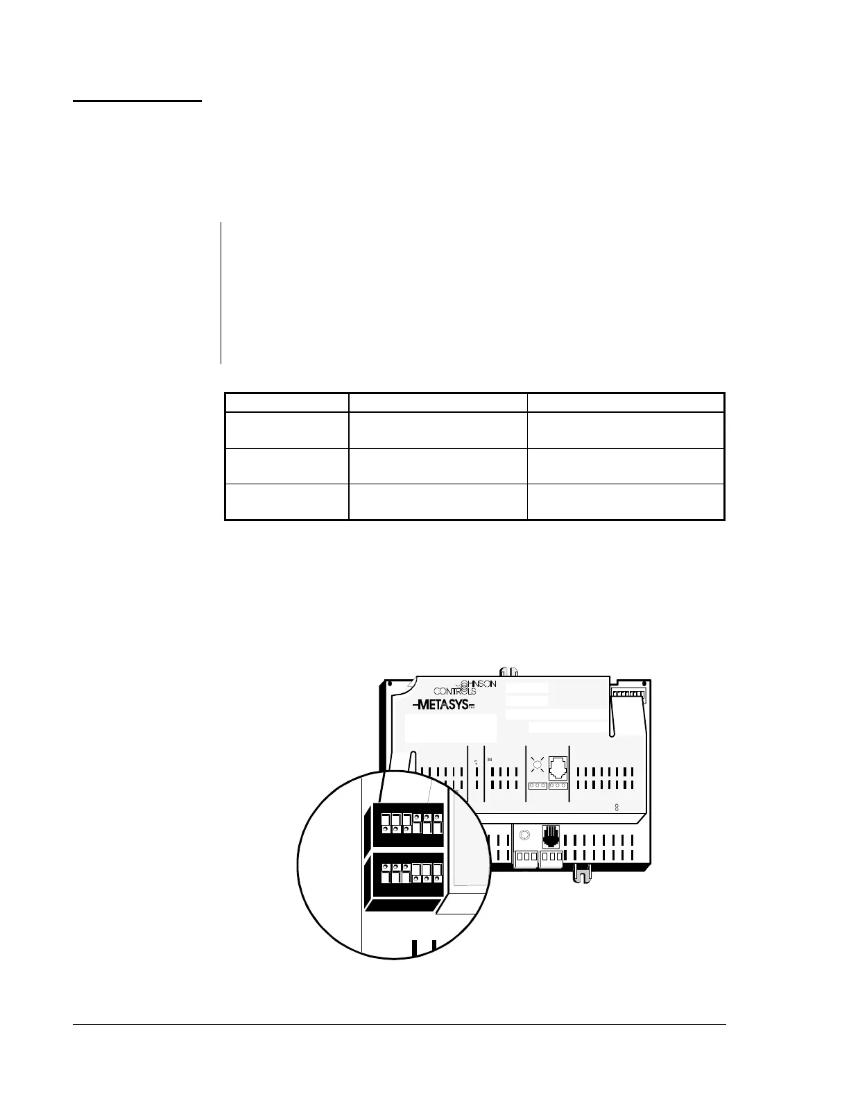
The six analog input terminals, their power supply, and their common
points occupy the lower left corner of the terminal strip. These inputs may
be of two types: resistive or voltage. The UNT processes and controls the
configured control strategy. It reads the analog inputs through the analog
input DIP switches located directly above the analog input terminals.
Use these switches and HVAC PRO for Windows to select the type of
analog input. Use the T position for all temperature sensors and setpoint
potentiometers. Use the V position for all active voltage transmitters. For
humidity applications using 3-wire voltage transmitters, such as the
HE-6300 Series, use the 15 VDC power supply terminals next to the
inputs for AI 6. Table 9 shows each configuration.
Table 9: Analog Input Configurations
AI Type Range Switch Position
Voltage (V)
0 to 2 VDC SW1 to Position V and SW2 to
Position 2V
Voltage (V)
0 to 10 VDC SW1 to Position V and SW2 to
Position 10V
Resistance /
Temperature (T)
1,000 ohm Nickel, Platinum,
Silicon, 2k ohm potentiometer
SW1 to Position T and SW2 to
Position 2V
The UNT has two sets of DIP switches. One set is for configuring the
analog input points, and the other set is for setting the controller address.
Use Table 10 to set analog input DIP switches. Instructions for setting the
N2 Address DIP switches are in the Networking the Controller section of
this technical bulletin.
1 2 3 4 5 6
1 2 3 4 5 6 7 8
BINARY INANALOG INPUTS BINARY OUTPUTS
70
BINARY INPUT
ANALOG INPUTS
1 2 3 4 5 6 1 2 3 4
ANALOG INP UTS
CO MMON
+15VDC
TO
ZONE
STAT
BINARY OU TPUT
24VAC
1 2 3 4 5 6
+15VDC
24VAC
COMMON
COMMON
REF
N2-
N2+
24VAC
COM
ZBU S
Z BUS
DSI
7 8
TRA CS
24 VAC
1 2 3 4 5 6
COMMON
COMMON
COMMON
Analog Input Switches
aiswtch2
ANALOG
V
T2V
10V
SW2
SW1
1 2 3 4 5 6
O
N
1 2 3 4 5 6
O
N
Figure 12: Setting the Analog Input DIP Switches
Analog Inputs
Setting the
Analog DIP
Switches
 Loading...