UNT Controller—Unitary Controller (UNT) 47
1 2 3 4 5 6
BINARY I NANALOG INPUTS BI NA RY O UTP UTS
70
BINA RY INP UT
ANALOG INPUTS
1 2 3 4 5 6 1 2 3 4
ANALOG INPUTS
CO MMO N
TO
ZONE
STA T
BI NA RY OUTPU T
1 2 3 4 5 6 7 8
Z BUS
DSI
1 2 3 4 5 6
BI NA RY CO M
1
2
36
5
4
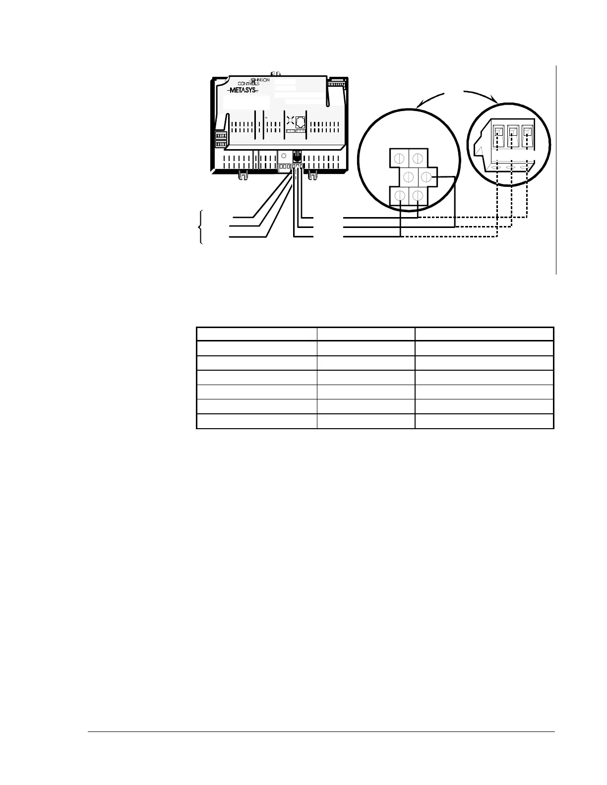
Note: Since the UNT is a self-terminating device, end-of-line termination
for the N2 Bus is not required.
N2 REF
N2 -
N2 +
N2 +
N2 -
N2 REF
NCU (TB1 on
Communication
Terminal Board)
HRD
GRD
SFT
GRD
N2-
N2+
REF
SFT
GRD
REF N2- N2+
n2wire-a
Figure 24: Connecting the UNT Controller to an NCM
Table 14: Terminal Locations
TB1 Terminal Function Number UNT Connection
Chassis Ground
6 None
Soft Ground
5 None
N2 Ref
4REF
Soft Ground
3 None
N2B -
2N2 Bus: N2-
N2B +
1N2 Bus: N2+
N2 Wiring to the
Network Control
Module
 Loading...