14969-02
8.31.2017
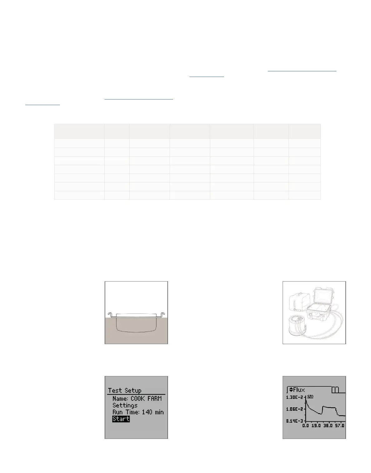
3. Set Up and Start Test
Power on the control unit. Press
Enter, create a unique test
name, and select Done. Input the
appropriate settings. Press BACK,
scroll to Start, and press Enter.
Confirm everything is properly
connected and select OK to
begin the test.
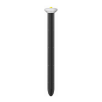
1. Install Insertion Ring
Place the insertion ring on the
soil and fit the driving plate on
the top. Hammer on the inner
circle of the driving plate until the
insertion ring is flush with the top
of the soil, ensuring there are no
gaps between the soil and ring
side walls. Remove the
driving plate.
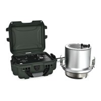
2. Set Up Infiltrometer Head
Fit the infiltrometer head to the
insertion ring, fasten the clamps to
form a seal, and connect the hoses
to the corresponding ports on the
infiltrometer head and the control
unit. Connect the sensor cable from
infiltrometer head to the control
unit. Fill the water tank and connect
it to the control unit.
NOTE: Avoid water intrusion into
the air hose as this can cause water
to enter the air pump.
Installation
SATURO QUICK START
Downloading Data
Install the downloader software at https://www.metergroup.com/
saturo-support.
After the test is completed, connect the control unit to a computer
via the USB cable and start the downloader software. Select the
proper COM port and click Download. The data can be formatted as
either a .xlsx or .csv file.
Preparation
Confirm that SATURO components are intact. Depending on the
research goals, SATURO will need access to water from the site or
to water of similar ionic strength for more representative soil–water
interactions.
Read the SATURO User’s Manual at https://www.metergroup.com/
saturo-support. All products have a 30-day satisfaction guarantee.
4. Reach and Maintain
Steady State
SATURO should reach quasi-
steady-state flow during the test.
If the test has reached steady
state, the flux remains constant
as the pressure is maintained and
changes as the pressure head rises
and falls. If the test does not reach
steady state, rerun the test with
different settings. For more
information, please refer to the
product manual.
Soil Type
Soak Time
(min)
Low Pressure Head
(cm)
High Pressure Head
(cm)
Hold Time at Pressure
(min)
Pressure Cycles
(count)
Total Run Time
(min)
Dry loamy sand 25 5 10 15 3 115
Wet loamy sand 15 5 10 15 2 75
Dry silt loam 30 5 15 20 3 150
Wet silt loam 15 5 15 20 2 95
Dry clay (poor structure) 30 5 20 25 3 180
Wet clay (poor structure) 15 5 20 25 2 115
Dry clay (strong structure) 25 5 10 20 3 145
Recommended measurement settings
NOTE: These settings are only a recommendation and should be altered depending on site conditions. If flux rates exceed 90 cm/h, decrease the low- and
high-pressure heads to decrease flow rates.
NOTE: Wet the soil after installing the insertion ring if soil is dry or infiltration is too high.
 Loading...