9
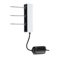
TEROS 12
If the TEROS 12 cable has a standard 3.5-mm stereo plug connector and will be connected to
a non-METER data logger, please use one of the following two options.
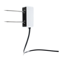
Option 1
1. Clip off the 3.5-mm stereo plug connector on the sensor cable.
2. Strip and tin the wires.
3. Wire it directly into the data logger.
This option has the advantage of creating a direct connection with no chance of the sensor
becoming unplugged. However, it then cannot be easily used in the future with a METER
readout unit or data logger.
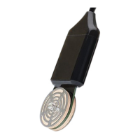
Option 2
Obtain an adapter cable from METER.
The adapter cable has a connector for the stereo plug connector sensor jack on one end and
three wires (or pigtail adapter) on the other end for connection to a data logger. The stripped
and tinned adapter cable wires have the same termination as seen in Figure3; the brown
wire is excitation, the orange is output, and the bare wire is ground.
NOTE: Secure the 3.5-mm stereo plug connector to the pigtail adapter connections to ensure the sensor does not
become disconnected during use.
2.3 COMMUNICATION
The TEROS 12 sensor communicates using two different methods:
DDI serial string
SDI-12 communication protocol
To obtain detailed instructions, read the TEROS 12 Integrator Guide.