14
SYSTEM
A ferrite core positioned on the TEROS 12 sensor cable 7.6 cm (3 in) away from the sensor
head is utilized to isolate the sensor from any interferences in the system. This mitigates any
potential noise from the system on the measured sensor data. It is important to not attach
anything to the section of cable between the sensor head and the ferrite core as this may
influence the measurements.
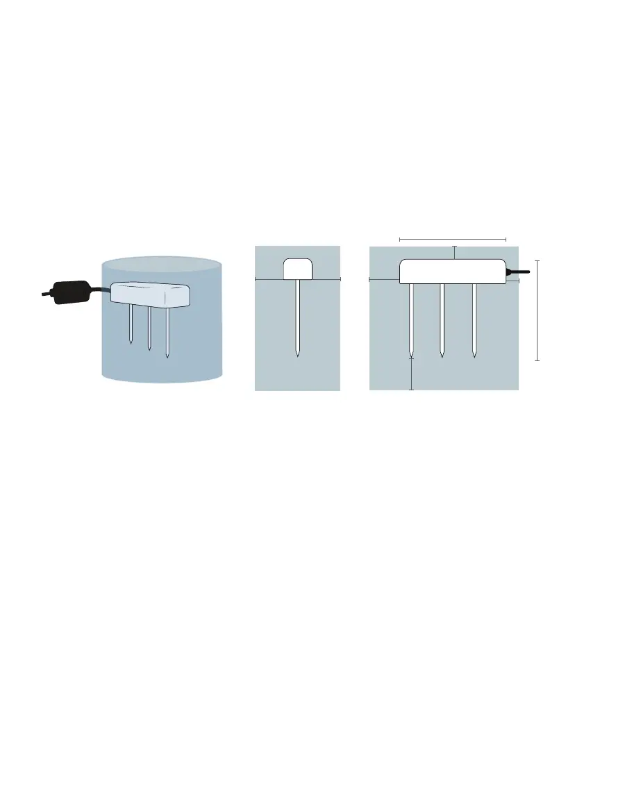
The TEROS 12 VWC measurement sensitivity is contained within a 1,010 mL volume roughly
depicted in Figure5. Please see the application note Measurement volume of METER
volumetric water content sensors (https://www.metergroup.com/environment/articles/
measurement-volume-meter-volumetric-water-content-sensors) for testing protocol and
more thorough analysis.
3 cm
3 cm
3 cm
1 cm
1 cm
7.5 cm
3 cm
Figure5 VWC volume of inuence
NOTE: The TEROS 12 provides instantaneous or near-instantaneous measurements; however, because of the
sensitivity of the measurement of the sensor head, the TEROS 12 is not well suited for spot measurements of VWC.
3.3 THEORY
The following sections explain the theory of VWC, temperature, and EC measured by
TEROS12.
3.3.1 VOLUMETRIC WATER CONTENT
TEROS 12 sensors use an electromagnetic field to measure the dielectric permittivity of the
surrounding medium. The sensor supplies a 70-MHz oscillating wave to the sensor needles,
which charge according to the dielectric of the material. The charge time is proportional to
substrate dielectric and substrate VWC. The TEROS 12 microprocessor measures the charge
time and outputs a raw value based on the substrate dielectric permittivity. The raw value is
then converted to VWC by a calibration equation specific to the substrate (Section 4.1).