4
OPERATION
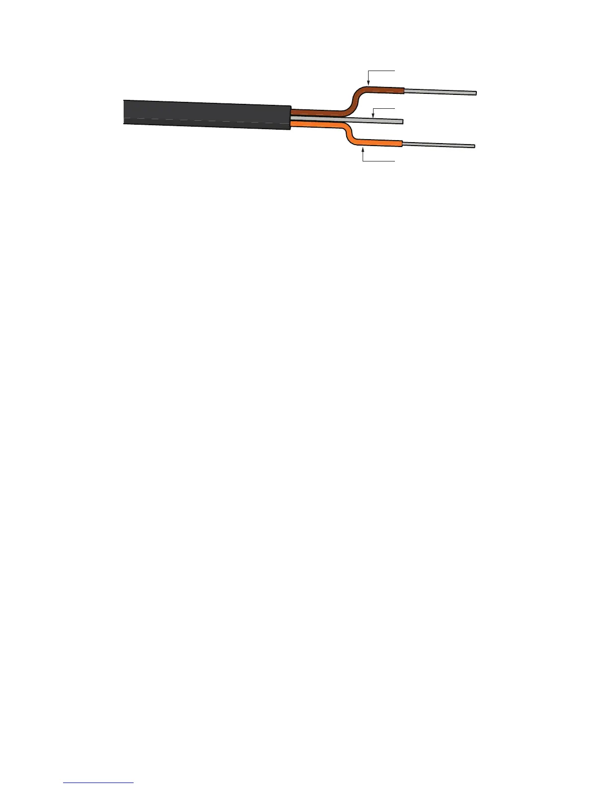
Ground (bare)
Data (orange)
Power (brown)
Pigtail wiring
NOTE: Sensors manufactured as MPS-6 use white wire for power and red wire for data output.
TEROS 21 sensors communicate using two different methods: serial (TTL) and SDI-12.
Please refer to the complete TEROS 21 Integrator Guide for more detailed explanations
andinstructions.
There are two options to connect a sensor with the standard stereo plug to a non-METER
data logger.
Option 1
1. Clip the plug off the sensor cable.
2. Strip and tin the wires.
3. Connect the wires directly into the data logger.
This will create a direct connection with no chance of the sensor becoming unplugged;
however, the sensor cannot be easily used in the future with a METER readout unit or
datalogger.
Option 2
Obtain an adapter cable from METER.
The adapter cable has a 3.5-mm stereo plug connector for connecting to the sensor on one
end and three wires for connecting to a data logger (a stereo-to-pigtail adapter) on the other
end. The stripped and tinned adapter cable wires have the same termination as seen in
Figure2; the brown wire is power, orange is output, and the bare wire is ground.
Because TEROS 21 sensors use digital communication, they require special considerations
when connecting to an SDI-12 data logger. Read SDI-12 example programs to view sample
Campbell Scientific programs.