EasyManua.ls Logo

Metra Electronics 95-8160G User Manual

Default Icon
8 pages
To Next Page IconTo Next Page
Page #1 background imageLoading...
Page #1 background image
INSTALLATION INSTRUCTIONS FOR PART 95-8160G
APPLICATIONS
METRA. The World’s best kits.
metraonline.com1-800-221-0932
© COPYRIGHT 2013 METRA ELECTRONICS CORPORATION
REV. 12/18/2013 INST95-8160G
CAUTION: Metra recommends disconnecting the
negative battery terminal before beginning any
installation. All accessories, switches, and especially
air bag indicator lights must be plugged in before
reconnecting the battery or cycling the ignition.
NOTE: Refer to the instructions included with the
aftermarket radio.
Table of Contents
• Double DIN radio provision
Painted gray to match factory color and finish
A) Radio Housing • B) Brackets • C) Panel Clip brackets (2) • D) Panel clip bracket screws (4) #4 x 3/8”
• E) Panel clips (2) • F) (4) #8 x 3/8” truss-head Phillips screws
KIT FEATURES
KIT COMPONENTS
WIRING & ANTENNA CONNECTIONS (sold separately)
Wiring Harness:TYTO-01 Axxess Interface
Antenna Adapter: • 40-LX11 antenna adapter and 44-EC204 antenna extension
Lexus LS430 2001-2006 (without factory NAV)
95-8160G
Dash Disassembly
Lexus LS430 2001-2006 ..................................... 2
Kit Assembly
Double DIN radio provision ................................... 3
• Panel removal tool • Phillips screwdriver
• Socket Wrench
TOOLS REQUIRED
A
B C D
F
E
Question and Answer IconNeed help?

Do you have a question about the Metra Electronics 95-8160G and is the answer not in the manual?

Metra Electronics 95-8160G Specifications

General IconGeneral
BrandMetra Electronics
Model95-8160G
CategoryAutomobile Accessories
LanguageEnglish

Summary

Kit Overview and Components

Applications

Specifies compatible vehicle models and years for the installation kit.

Kit Features

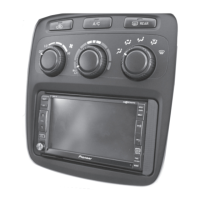
Highlights key attributes of the installation kit, such as radio provision and color matching.

Kit Components

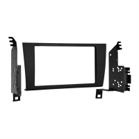
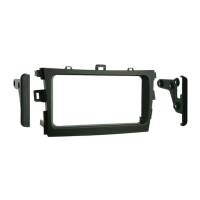
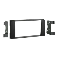
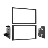
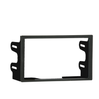
Lists all physical parts included in the installation kit with their identifiers.

Tools Required

Details the necessary tools for performing the installation.

Wiring and Antenna Connections

Identifies required wiring harnesses and antenna adapters for system integration.

Dash Disassembly Procedure

Remove Heated Seat Switch Panel

Step to detach the heated seat switch panel as the initial disassembly action.

Remove Tray Assembly

Procedure for removing the tray assembly after releasing three screws and unclipping.

Remove Factory Radio Bolts

Instruction to remove two 10mm bolts securing the factory radio unit.

Kit Assembly Procedure

Attach Brackets to Radio Housing

Mounting the provided brackets to the radio housing trim panel using screws.

Install Radio into Housing

Sliding the radio into the assembled housing and securing it.

Mount Panel Clip Brackets

Attaching panel clip brackets to the radio housing using specific screws.

Attach Panel Clips

Securing white plastic panel clips to the mounted panel clip brackets.

Connect Wiring and Test

Locate factory harness, connect adapter, reconnect battery, and test operation.

Antenna Connection Routing

Note on routing the factory antenna connection from the trunk tuner brain.

Reassemble Dash

Instruction to reassemble the vehicle's dashboard in the reverse order of disassembly.

Related product manuals