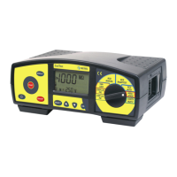
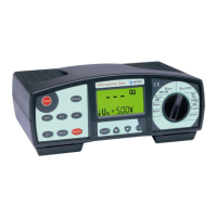
MI 2088 Earth –Insulation Tester Measurement instructions
12
3. Measurement instructions
3.1. Insulation Resistance
There are different objects, where Insulation Resistance is to be measured, in order to
assure safety of electric installation and appliances. Let’s list a few examples:
• Insulation Resistance between installation conductors L1, L2, L3, N, PE (all
• combinations).
• Insulation Resistance of non-conductive rooms (walls and floors).
• Insulation Resistance of ground cables.
• Resistance of semiconductive (antistatic) floors.
For additional general information concerning Insulation Resistance measurement,
refer to enclosed handbook Measurements on electric installations in practice and
theory.
Warnings!
• Make sure tested object to be deenergized (mains voltage disconnected) before
starting the measurement!
• When measuring Insulation Resistance between conductors, all loads must be
disconnected and all switches closed!
• Do not touch tested object while testing it, risk of electric schock!
• Do not connect test terminals to external voltage higher than 600 V a.c. or d.c.,
in order not to damage the test instrument!
• In case of capacitive test object (capacitive compensation of reactive power,
long tested cable etc.), automatic discharge of the object may not be done
immediatelly after finishing the measurement. Falling voltage will be displayed in
that case – do not disconnect test leads until the voltage drops below 50V!
How to carry out the measurement ?
Step 1
• Connect test cable (Split test leads or Tip Commander) to Earth - Insulation
Tester.
• Set function switch to RINS, VOLTAGE position, the following menu will be
displayed:
 Loading...