Doc# 90018-031 • REV L (April 2016) Page 2 of 16
NOTE: Discrete outputs should be manually bypassed during
this procedure, parcularly if used to trip the machine. They will
change state aer the me delay, and should be externally jump-
ered or otherwise disabled to prevent nuisance trips.
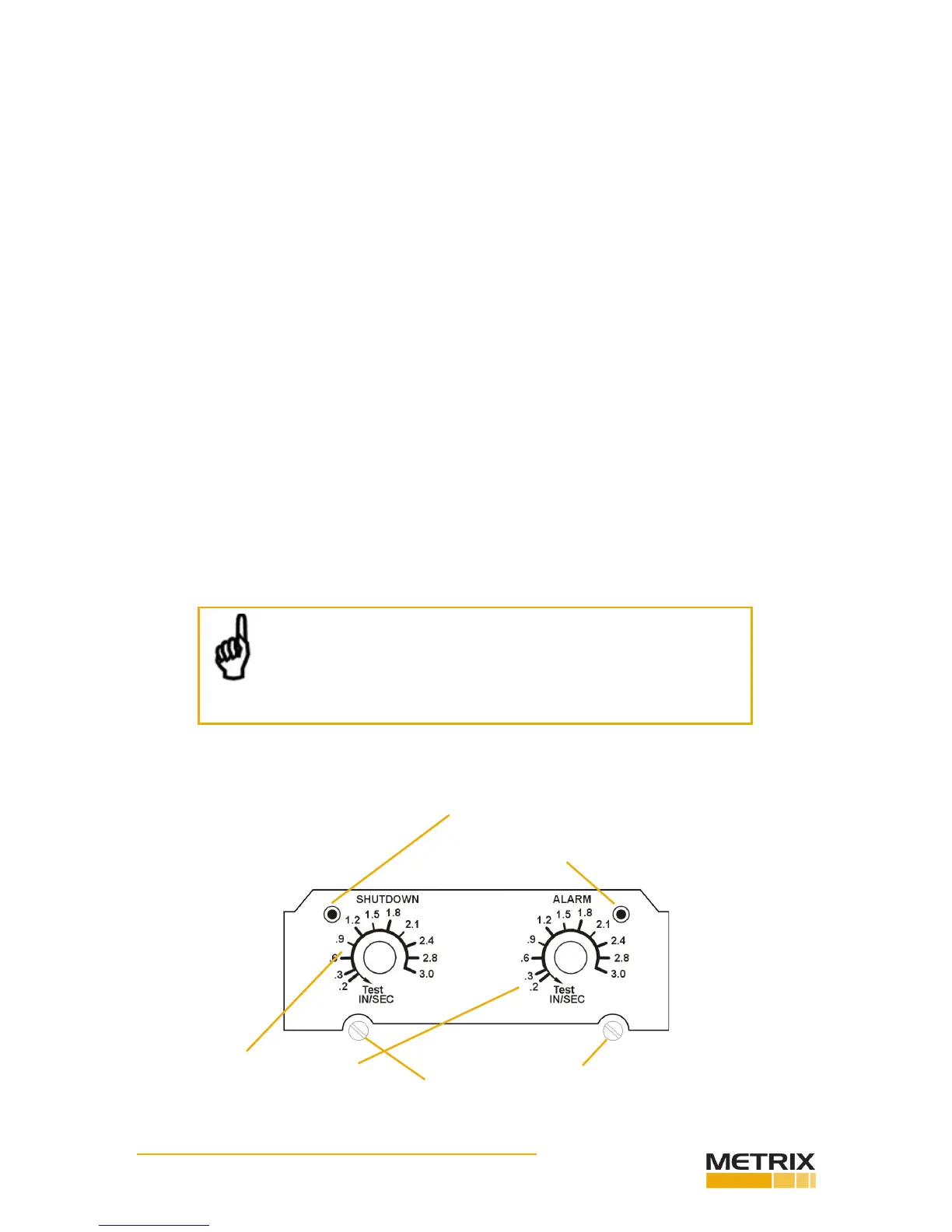
Calibrated setpoint controls
enable operator to set specic
velocity alarm/shutdown levels.
Adjustable me delay of 2-15 seconds.
LED illuminates immediately when vibraon ex-
ceeds setpoint (but alarm or shutdown discrete
outputs will change state only aer me delay).
1.3UserInterface
KeyCapabilies(connued)
switches have dual setpoints – one for alarm and one for shutdown – that are indepen-
dently adjustable.
• 4-20 mA output provides a convenient interface for trending and displaying vibraon
amplitude in a programmable logic controller (PLC), SCADA system, data logger, or oth-
er instrumentaon. 4mA corresponds to no vibraon, and allows the user to disnguish
between no power to the switch (0mA) and a funconal switch but with no vibraon
present (4mA). 20mA corresponds to full scale vibraon amplitude.
• Discrete outputs used for alarming and shutdown can be selected from triac, solid-
state analog switch (FET), or electromechanical relays, but must be specied at me of
ordering. These outputs are independently congurable for open on alarm/shutdown
or close on alarm/shutdown .
• An adjustable (2-15 seconds) me delay is standard. This prevents false alarms/shut-
downs on high startup vibraons and also from non repeve transient events.
• Self-test and vericaon: An LED adjacent to each setpoint control illuminates the
instant the measured vibraon level exceeds the setpoint. The unit can be periodically
veried on line by turning the setpoint control down unl the LED comes on. This set-
ng is then compared with the vibraon amplitude measured via a portable vibraon
meter at the same locaon as the switch’s sensing element, providing a vericaon
check of the unit.
 Loading...