Doc# 90018-031 • REV L (April 2016) Page 4 of 16
4. MECHANICAL INSTALLATION
4.1 Where to Mount the Switch
It is desirable to mount the electronic switch (or transducers for switches with external
transducer opon) on a bearing housing, since the forces generated by the rotang parts
through unbalance, misalignment, bearing wear, etc., are transmied to the machine’s cas-
ing through the bearings.
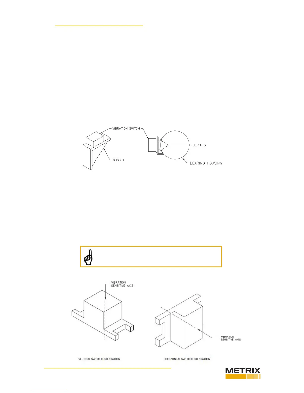
Most bearing housings are curved so it is necessary to aach a bracket with a at surface for
mounng the switch. If the machine has bolted end plates on the bearings or horizontally
split bearing housings, these bolts can be used to aach the bracket.
When bolt holes are not available or are not suitable, an alternave way is to weld an angle
iron bracket similar to that in the sketch, but oriented so as to straddle the bearing housing.
The best approach will typically be to mount a gusseted bracket, as shown below.
The guiding principle is to ensure that the bracket is suitably s such that machinery
vibraon is completely transmied through the bracket to the vibraon switch or sensor.
Problems can occur when the bracket is too compliant, and may allow bracket resonance
to amplify the actual machinery vibraon, resulng in false shutdowns or alarms. For many
applicaons, 3/8 Inch material (preferably steel) will be suitable.
4.2 SwitchSensiveAxis
The sensive vibraon “measuring” axis is perpendicular to the mounng base of the unit
(vibraon switch or transducer). Always mount the unit such that the desired vibraon of
the equipment being monitored will occur along this axis.
NOTE: Models using an external sensor will be sen-
sive along the sensor’s axis, not the switch’s axis.