Doc# 90018-031 • REV L (April 2016) Page 5 of 16
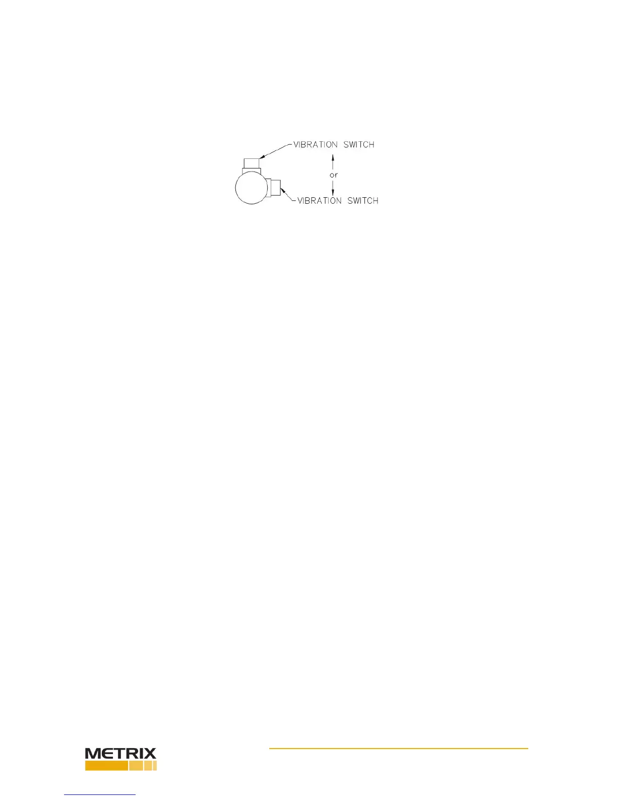
4.3 ChoosingMounngOrientaon
The vibraon switch can be mounted in the vercal or horizontal orientaon (or anything in
between) without a change in its sensivity. Ideally, the mounng orientaon will be chosen
by measuring the vibraon levels in both direcons with a vibraon meter and then select-
ing the direcon in which the highest vibraon occurs. This will typically be horizontal, since
most machine structures are less rigid horizontally than vercally.
4.4 NumberofPointsperMachine
Anywhere from one to four switches are used per machine (depending on how crical the
machine is to the process or how expensive it is), one on each end of the motor and one on
each end of the compressor, fan, pump or whatever is being driven. If there is a gear box in
between, one may be used here also.
It is quite common to use only one switch. In this case, it is best to mount on or near the
driven bearing. For example, if you have a motor and large fan with a bearing on each end
of the fan, the fan bearing on the motor side would be the driven bearing. It will usually see
the highest forces and have the highest vibraon level.
4.5 MounngatotherLocaons
When it is not possible to mount the switch directly on the bearing housing, the switch can
be located elsewhere, keeping in mind that it is usually machinery vibraon that is being
measured (not bracket, piping, or other vibraon). Do not mount the switch in locaons
where very lile machinery vibraon is transmied, as the switch will be less sensive to
damaging changes in machinery vibraon levels. Again, it is desirable to survey the machine
with a vibraon meter. If the level at the intended locaon is not aenuated by more than
about 50% relave to the levels directly on the bearing housing, it will probably be sasfac-
tory. However, alarm and shutdown sengs should then be reduced proporonately as well.
4.6 MounngSurface
Choose or fabricate a solid (rigid) surface (on the equipment being monitored) to mount
the vibraon switch or transducer. This will ensure transfer of the vibraon to the vibraon
transducer, while not introducing erroneous vibraons. In addion, the surface presented to
the base of the unit should be at. Fasten using sturdy hardware at all places provided.
4.7 TemperatureConsideraons
The switch is designed to dissipate internal heat by conducon through its base. Hence, it is
important to keep the mounng surface below the switch max temperature limit of 140°F. If
the equipment being monitored is going to exceed this limit, consideraon should be given
to either using one of the remote transducers, or thermally isolang the switch. To ensure
accurate switch performance, a warm up me of 5 minutes is recommended.
4.8 ElevaonConsideraons
The reduced atmospheric pressure at elevaons more than 2,000 meters (~6600 feet) above
 Loading...