Doc# 90018-031 • REV L (April 2016) Page 6 of 16
sea level does not allow heat to dissipate as readily as at lower elevaons, and the maximum
operang temperature must be de-rated by 2% per 300 meters. Thus, a switch installed at
an elevaon of 2,600 meters will have a maximum operang temperature 4% lower than
a switch installed between seal level and 2,000 meters. Refer to datasheet 1004730 for
complete specicaons.
4.9 Cable/Wiring
The method chosen to electrically connect to the switch or transducer should be mechani-
cally exible, to eliminate the measurement of vibraon of material not of interest (piping,
etc.), and provide a moisture barrier as well.
Although seal ght and other exible conduit have been used successfully, in areas of
extreme humidity or moisture it is recommended that a “SO” type cable together with a
suitable rain-ght CGB ng be used.
No stress should be possible on the wiring to the terminal block. If such protecon is not
provided by the conduit system, some form of stress relief must be installed where the wir-
ing exits the 440.
To reduce suscepbility to EMI/RFI, any signal-level wiring such as transducer, reset, lockout,
or 4-20 mA loop should ulize shielded cable in EMI-proof conduit, separate from any power
wiring. The signal-wiring conduit and power-wiring conduits can be connected at the switch
entry via a “T” ng.
4.10 Sealing
In installaons where temperature and humidity condions vary around the dew point, it is
important that the cover be evenly and rmly fastened down with the four screws provided
(model 440) or via the threaded cover (model 450).
Although the switch enclosures meet NEMA standards for water ghtness, this assumes the
cover is properly seated and wiring/conduit entrances use proper seals.
5. ELECTRICAL INSTALLATION
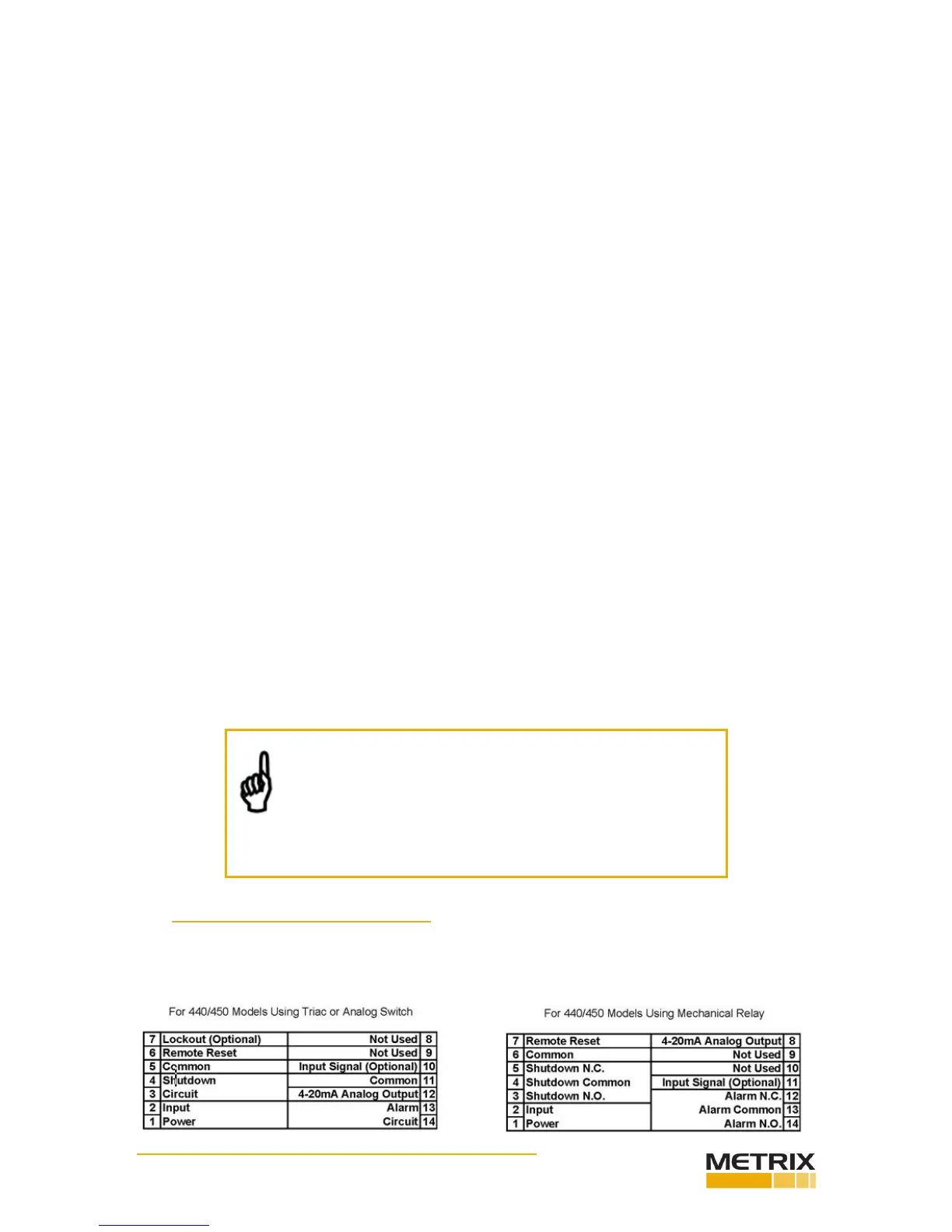
5.1 WiringtotheVibraonSwitch
See terminal numbering legends below. Refer also to the wiring diagrams of secon 8.
NOTE: Unless proper drains and/or poured seals are used,
conduit can allow moisture entry into the switch. Use good
installaon pracces that slope conduit away from the
switch, use drains (non-XP installaons only), and make
certain that cable jackets are not nicked or scued which might
allow moisture to wick into the switch via the conductors.
 Loading...