Doc# 90018-031 • REV L (April 2016) Page 3 of 16
NOTE: Turning either adjustment knob to the TEST posion reduces
the corresponding setpoint to its minimum allowable value, eec-
vely meaning that any vibraon will exceed the setpoint. Although
the LED will come on immediately, the discrete output will change
state only aer the duraon of the adjustable me delay has elapsed.
If the TEST posion is maintained for less than the duraon of the me delay,
the discrete output will not change state.
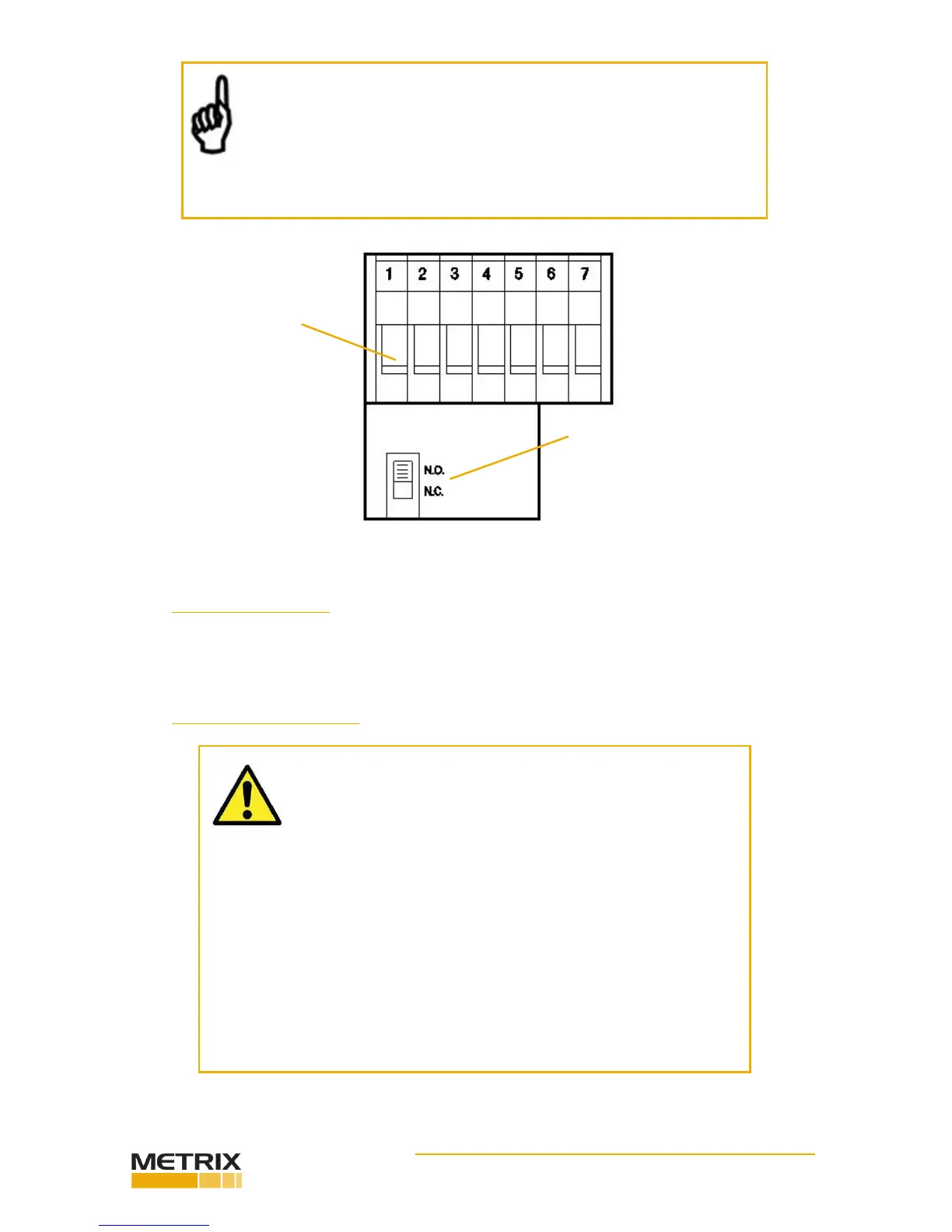
VDE approved terminal strip
accepts #12 AWG wire. All
hardware is capve.
Each discrete output is inde-
pendently eld congurable to
open on alarm (N.C.) or close
on alarm (N.O.)
3. SAFETY WARNINGS
CAUTION - SHOCK HAZARD 230/110 VOLTS
The terminal block inside the 440 is connected to AC power
(110 VAC or 230 VAC depending on model) except DC input
power models.
If adjustments to the device are being made with power applied, exer-
cise cauon to avoid contact with the terminal block screws by any part
of the body or electrically conducve tool.
EQUIPMENT OPERATION
Model 440 and 450 vibraon switches must be installed and operated
as described in this manual and in accordance with published datasheet
specicaons. Operaon outside these limits may adversely aect the
switch’s alarming and shutdown capabilies, resulng in damage to
machinery and property as well as jeopardizing personnel safety.
2. SPECIFICATIONS
Refer to product datasheet 1004730, available online at www.metrixvibraon.com.