Doc# 0296-0018 • REV R (July 2017) Page 57 of 61
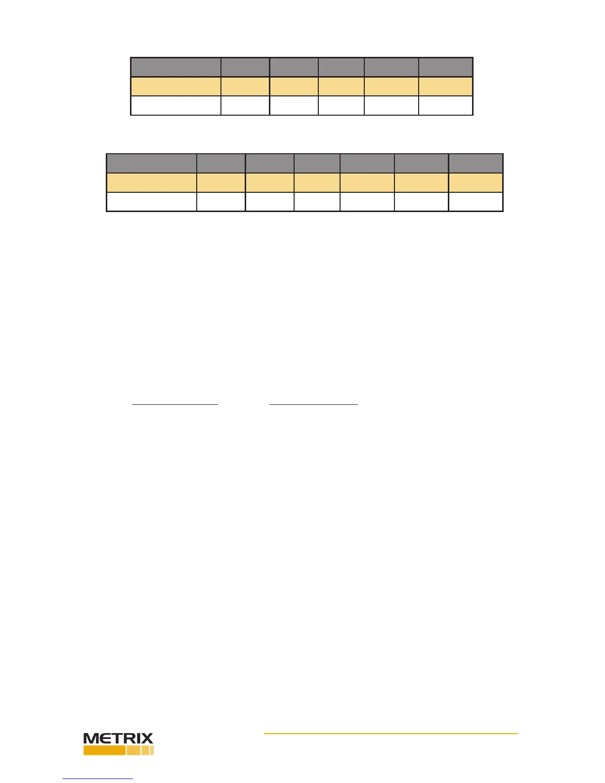
Reference Level 0.2 ips 0.4 ips 0.6 ips 0.8 ips 1.0 ips
Test Number A B C D E
Actual Level
TABLE 5-8: LINEARITY CHECK - FREQUENCY 100 HZ
Velocity Pickup
Frequency (Hz) 30 50 70 100 200 400
Test Number A B C D E F
Actual Level
TABLE 5-9: FREQUENCY RESPONSE CHECK - REF. LEVEL 0.2 IPS
Cable and Connector Checks
Following any vibraon performance checks made for transducers and their measurement systems, it
is always a good idea to check for cable and connector integrity by running the TTS at a high frequency
and at a moderate-to-high vibraon level while checking for possible signal interrupons that would
occur if looseness was present. Looseness may not be detected at low frequencies but can become very
detectable at higher frequencies.
Quick Check Procedure
The TTS can be used to funconally check for measurement accuracy
by comparing readings on the display for Acceleraon, Velocity and Displacement at crossover frequen-
cies. These three readings are derived from the reference accelerometer signal output and must be
compared with an instrument that is also calibrated to read similar engineering units.
Crossover Frequency Readings to Compare
61.44 Hz 1 g = 1 ips
44.3 Hz 5 g = 50 Mils pk-to-pk
29.3 Hz 5 ips = 50 Mils pk-to-pk
An alternate quick check can be made by seng the TTS to 1 g at 100 Hz and reading the reference ac-
celerometer output. An rms voltmeter should indicate 35.35 mV rms or an oscilloscope should indicate
50 mV peak (100 mV pk-to-pk).
Built-In-Test (BIT) Test Mode
Step 1. Press the MODE buon unl the BIT MODE screen appears.
NOTE: The arrow in the upper right corner is for factory installed opons and has not funcon under
normal operaon.
Step 2. Press the RUN/STORE buon to start the BIT test. While running the test the TTS will simultane-
ously display and print the results.
Step 3. If a BIT test fails, an asterisk (*) appears in the le hand mar gin.
TTS Blink Range Summary
The following table shows boundaries for operaon where the display does not blink the display blinking
feature has been incorporated to warn the operator that the unit is being operated beyond frequency
lim- its for the type of measurement or there may be some deterioraon of specied parameters, such
as amplitude accuracy and signal distoron.
 Loading...

