Doc# 100576 • REV C (Sept 2017) Page 26 of 42
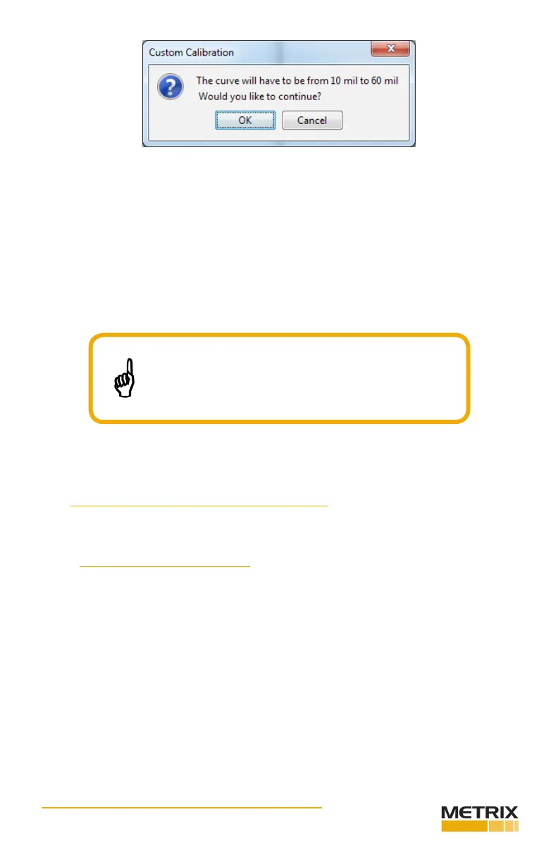
If this occurs, verify that the voltages you entered were correct. Verify that your system
components combine to the correct length. If all is correct, you can choose to accept the
shortened curve or hit cancel and use a dierent probe and cable. In some cases, probes
and cables that are far out of specicaon can be brought into specicaon by iterang the
custom calibraon process several mes.
4.2.1
Follow the steps in this secon to verify the current loop output for Posion or Radial Vibra-
on congured DPS units.
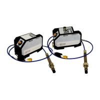
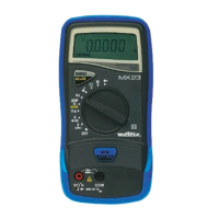
4.2.1.1 POSITION CONFIGURED UNITS
The transmier current output is linearly proporonal to the average probe gap (posion)
between 4 mA and 20 mA. Use the instruments and equipment shown in Figure 23 to verify
a posion transmier current output.
Metrix does not recommend using the custom
calibraon feature to calibrate mismatched systems. Mis-
matched systems degrade probe and cable temperature
performance.