SECTION 4 - COUNTERSHAFT, CTRSHAFT BOX & SHEAVE ASSEMBLIES
MP SERIES CONE CRUSHER TECHNICAL REFERENCE MANUAL
4-3
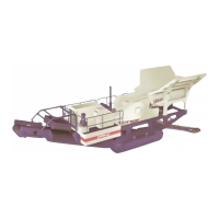
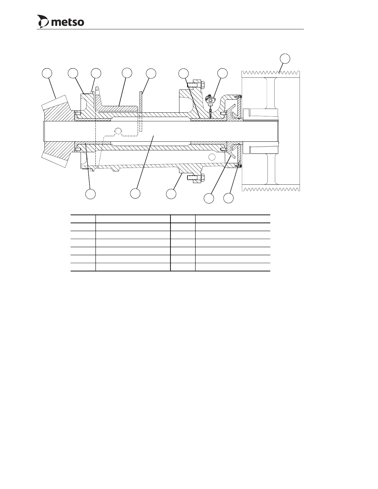
Figure 4-2 Countershaft, Countershaft Box and Sheave Assembly (MP800)
On the MP1000 only apply a sealant,
Silastic RTV732 (or equivalent) to the inner
surface of box flange and install seal. Then
install the rectangular seal and apply Silastic
RTV732 to exposed face of rectangular seal
just prior to installing box into frame. Refer
to Figures 4-2, 4-3 and 4-4.
4. With an overhead crane and suitable lifting
slings, lift the countershaft box assembly
and carefully insert it into the frame as far as
possible. Then lower the box and allow the
countershaft box pinion end flange to rest on
the frame.
5. Remove the sling from the pinion end of the
box. Then lower the sling, just removed,
through the inside of the frame to raise the
pinion end of the box.
6. Slide the box toward the inner frame, fit as
far as possible keeping the box centering lug
centered on the frame support guide pad.
Refer to Figure 4-5.
Callout Description Callout Description
1 Pinion 7 Sheave assembly
2 Wear ring 8 Countershaft
3 O-ring 9 Countershaft box
4 Box guard 10 Oil flinger
5 Box shield 11 Countershaft box cover
6 Bushing 12 Countershaft bushing RTD
1 2 3
4
5 6
7
12
11
10
8
9
6
 Loading...