Do you have a question about the Meyer Sound Compact VariO UPJ-1P and is the answer not in the manual?
Guidance on navigating the manual, understanding icons, and interpreting safety warnings.
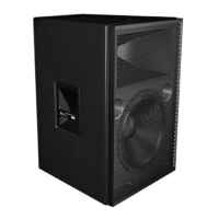
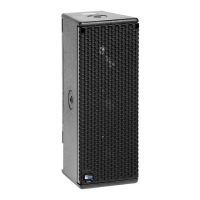
Overview of the UPJ-1P's features, design, construction, and intended applications.
Details the UPJ-1P's AC power connection, including the PowerCon connector and daisy-chaining capabilities.
Specifies the acceptable AC voltage range (90-264 V AC) and system behavior during power application.
Explains current draw types (long-term, burst, peak) essential for system planning and breaker selection.
Provides guidelines for correctly wiring AC power connectors, emphasizing grounding for safety.
Crucial safety warnings regarding grounding, correct plug usage, and potential electrical hazards.
Describes the balanced XLR input, impedance, and wiring for audio signal connections.
Details the function of the looping audio input module, including its connections and signal path.
Explains the module with polarity switch and level attenuator for flexible audio input control.
Covers the amplifier's two-channel design, limiting functions, and driver protection mechanisms.
Explains the natural convection and forced air cooling system that maintains amplifier temperature.
Introduces the RMS communication module's user panel and its LEDs and buttons.
Describes the function of the red Service LED, indicating network status or hardware faults.
Explains the function of the Service Button for system identification and potential decommissioning.
Details the green Wink LED used to identify loudspeakers remotely via the RMS software.
Explains how the Reset Button is used to reboot the RMS card firmware without affecting commissioning.
Describes the green Activity LED, indicating the loudspeaker's commissioned status on the network.
Overview of the RMS software's graphical interface for monitoring loudspeaker parameters and system status.
Explains daisy-chaining UPJ-1P loudspeakers and subwoofers for system connection and frequency response.
Details using a line driver to adjust gain and polarity for subwoofers and UPJ-1Ps for system integration.
Instructions on using the Lo-Cut filter with UPJ-1Ps and subwoofers to achieve a flat frequency response.
Discusses the optional use of DSPs with UPJ-1Ps and subwoofers, noting potential phase shift issues.
Introduction to MAPP Online, a powerful tool for acoustical prediction and system design.
Overview of SIM, an instrumentation system for acoustical measurement, analysis, and system alignment.
Explains SIM's dual-channel technique for measuring systems with unpredictable excitation signals.
Lists various applications for the SIM system, including loudspeaker testing, calibration, and acoustics.
Step-by-step guide on how to rotate the UPJ-1P's Vario horn for 80° x 50° coverage patterns.
Describes basic rigging methods using eyebolts for single or two-hole configurations on the UPJ-1P.
Instructions for pole-mounting a single UPJ-1P using third-party pole-mount adapters.
Details on using L-brackets for mounting the UPJ-1P to walls, ceilings, or floors for versatile placement.
Specific guidance for wall mounting the UPJ-1P in both vertical and horizontal orientations.
Instructions for securely mounting the UPJ-1P in ceiling, underbalcony, or canopy areas.
Method for mounting the UPJ-1P on floors or stage lips, useful for monitoring or front-fill applications.
Information on using a cradle-style yoke assembly for suspending and adjusting a single UPJ-1P.
Guidance on using the array adapter for creating horizontal and vertical arrays of UPJ-1P loudspeakers.
How to configure horizontal arrays with the MAA-UPJ adapter, detailing splay angles and coverage.
Instructions for pole-mounting a horizontal array of two UPJ-1Ps using compatible adapters.
Methods for flying horizontal arrays using eyebolts attached to the MAA-UPJ adapter.
How to configure vertical arrays with the MAA-UPJ adapter, detailing splay angles and coverage.
Instructions for mounting a vertical array of UPJ-1Ps to the ceiling using the MAA-UPJ and MLB-UPJ.
Methods for flying vertical arrays using eyebolts attached to the MAA-UPJ adapter for support.
Provides solutions for common problems encountered with the UPJ-1P loudspeaker.
Troubleshooting steps for when the unit has no power indication or audio output.
Steps to diagnose no sound issues when the unit is powered on and the LED is green.
Solutions for identifying and resolving hum or noise issues originating in the audio signal path.
Steps to address audio distortion or compression when the limit light is not active.
Guidance for resolving issues of constant limiting and audio compression due to signal levels.
Troubleshooting steps for when the On/Temp LED indicates the amplifier is overheating.
Steps to diagnose issues where only one of the loudspeaker drivers is producing sound.
Detailed technical specifications for the UPJ-1P loudspeaker, covering acoustical, transducer, and input parameters.
| Brand | Meyer Sound |
|---|---|
| Model | Compact VariO UPJ-1P |
| Category | Speakers |
| Language | English |