3
CHAPTER 2: PULL BACK RIGGING INSTRUCTIONS
Executing a pull back requires balancing the loads of suspended arrays. By altering the momentary load on each motor to
achieve a new stable configuration, this dynamically shifts the array’s center of gravity. These procedures ensure a safe tran-
sition from top grid suspension to full pull back.
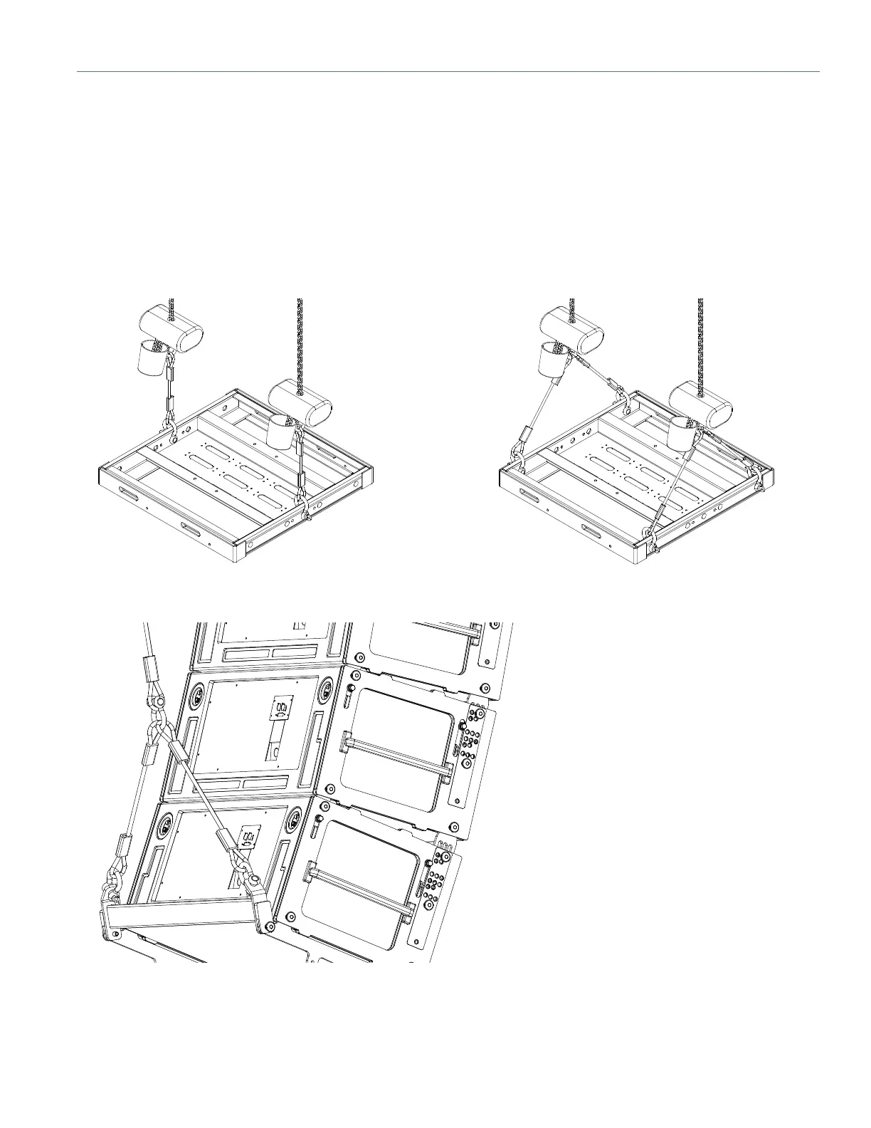
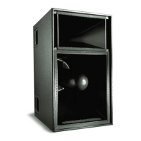
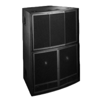
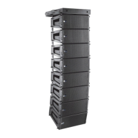
NOMENCLATURE
The following figures define the rigging points used in these instructions.
Top Front and Rear of Array Center Rigging Points (left); Top Front and Rear of Array Bridled Rigging Points (right)
Rear View of Bridled Pull-Back Points