Self-Powered Concert Series
Service Manual
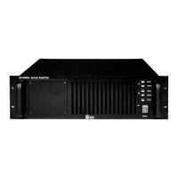
MP-2/4 Amplifier
Doc #: 05.033.040.01
Rev.: A
Date: 08/31/98
Page: 14 of 26
© 1998 Meyer Sound Laboratories, Inc. All rights reserved.
If any of the previous three conditions (step 8) are not met, continue to step 11.
Note: If you are going to replace the Amp/heatsink module, make sure that the AC Mains board is in good
condition and not stressed, checking the thermistor for cracks or visible burns. If the thermistor is damaged the
AC Mains module should also be replaced. (Use steps 11 to 13 to gain access to the AC mains board). The drivers
should also be tested; refer to Driver Inspection and Evaluation Procedure for Self Powered Series Products
(Low Driver #17.010.120.01 and High driver #17.010.120.02).
10. You may perform the following procedure to determine if MOSFETs on the Amp/
heatsink module are shorted.
Caution: Never disassemble the amplifier PCB board from the heatsink.
MP-2 Amp/heatsink module evaluation:
a) Allow the Amp/heatsink module to discharge any residual voltage (about 3 minutes).
b) Remove the Control board from the Amp/heatsink module by disengaging the locking
standoffs and remove the 15 pin header from the header connector.
c) Locate the top side of the board MOSFETs Q4A, Q1A, Q2A, Q5A, Q4B, Q1B, Q2B, Q5B. They
are 8 large devices mounted on the heatsink sink each with 3 leads connecting to the board.
d) Using an ohmmeter (set to ohms, not diode check), measure the resistance between the drain
and source of each FET.
Note: Each FET will have three leads - Gate, Drain, and Source. The Gate is the one with the square pad
on the board, while the Drain and the Source are the ones with the round pads.
e) If any FET has a resistance of less than 5 ohms, the Amp/heatsink module will need to be
replaced.
f) If the Amp/heatsink module is found to be good, replace its Control board, and install the
Amp/heatsink module into the chassis.
Caution: When plugging the large white DC power connector into the amp board. Make sure the
connector is not shifted over one pin to the left or right. Also support the board to prevent bending.
g) Repeat the power up sequence as listed in step 8.
h) If the unit still will not power up, it is likely that the Amp/heatsink module has damage to
circuits other than the MOSFETs. Remove the Amp/heatsink module and replace it.
11. If any of the previous three conditions (step 8) are not met, the AC mains board or the
Power Supply could be damaged. If this is the case, continue to step 12.
12. To assess the power supply system, unplug the unit and allow the supplies to bleed
(about 3 minutes). Remove the eight (8) small head screws from the user panel and remove
the panel. Removethe audio signal cable from the audio input board by disengaging the
locking gray connector. Also remove the AC input cable from the AC mains board (4 wire
green connector).
13. Remove the sense cable (gray ribbon cable) and the transformer primary connector (8
wire green connector) from the AC mains board.