Self-Powered Concert Series
Service Manual
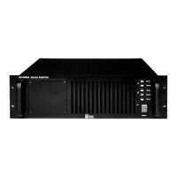
MP-2/4 Amplifier
Doc #: 05.033.040.01
Rev.: A
Date: 08/31/98
Page: 20 of 26
© 1998 Meyer Sound Laboratories, Inc. All rights reserved.
10. While firmly holding the AC mains board, remove the three (3) screws on the top of the
chassis and remove the board.
11. If the unit was subjected to overvoltage conditions (> 270 VAC), the AC mains board fuse
could be damaged. Locate the fuse (F1) on the AC mains board (between Relay 1 and the AC
input connector) and check the continuity with an ohmmeter. If the fuse is open, the AC
mains board will have to be replaced. Refer to Meyer Sound Self Powered Series MP-2/4 AC
Mains Service Procedure (# 17.033.022.01).
12. If the AC mains appears to be fine, try replacing the board with a known good one (either
a new one or from another unit). Install the good board and repeat the power up sequence
described in step 7.
13. If the unit still will not power up, it is likely that the power supply sub-module is
damaged. As power supply sub-module failures are rare, it is recommended that you return
the unit to the nearest authorized service center for further evaluation.
This condition is typically an indication of partial MOSFET failure. Generally, when one side
of a two channel amplifier has shorted MOSFETs, a large DC offset is created on that side
from the voltage supply rails. The amplifier sensing circuits detect this condition on power-
up, send a fault signal, and the amplifier shuts off. Please refer to Section A for troubleshoot-
ing information.
Note 1: If the unit is excessively hot (i.e. the heatsink > 80
°
C), it will shut off. Let the unit cool
sufficiently and try again.
Note 2: If the unit exhibits this condition and the TELO number on the Amplifier/heatsink module
is between 4400 and 5000, there may be a resistive bridge due to contamination on the traces near C2
and Q9. This was corrected by a jumper wire between R27 and C16 on the Amp/heatsink module. If
the Amp/heatsink module is in the mentioned range and does not have the jumper, the module needs
to be replaced.
Note 3: If the unit only exhibits this condition occasionally, it may be a temperature sensor on the
Amp/heatsink sub-module. On older units, prior to June 1995, the temperature sensor occasionally
caused a false fault trigger on power up. This was corrected by a resistor change on the Amp/heatsink
module. Locate R38 on the circuit board (top left edge of the board) and check the value. It should be
1.5k (color code: Brown, green, black, brown, brown [1% tol.] ). If the value is incorrect, the Amp/
heatsink module should be replaced.
C. Unit powers up and immediately shuts off: