Self-Powered Concert Series
Service Manual
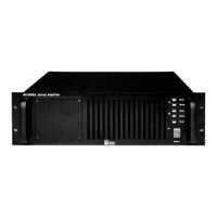
MP-2/4 Amplifier
Doc #: 05.033.040.01
Rev.: A
Date: 08/31/98
Page: 15 of 26
© 1998 Meyer Sound Laboratories, Inc. All rights reserved.
4-Channel Versions
14. While firmly holding the AC mains board, remove the three (3) screws on the top of the
chassis and remove the entire board.
15. Replace the AC mains board with a known good board (either new or from another unit).
Make sure to reconnect the sense cable and the transformer primary connector. Replace the
user panel and repeat the power up sequence as stated in step 8.
16. If the three conditions stated in step 8 are met this time, the Power Supply circuits are
probably functioning properly. It is most likely that the AC Mains Board is damaged and
will need to be replaced. You can refer to Meyer Sound Self Powered Series MP-2/4 AC
MainsService Procedure (#17.033.022.01) for replacement procedures for the AC Mains
board.
17. If the unit still does not power up properly, it is likely that the Power Supply module
is damaged. As Power Supply module failures are rare, it is recommended that you
return the unit to the nearest authorized service center for further evaluation.
1. Do not reset the circuit breakers. If the circuit breakers are reset without first determining
the cause, further damage to the electronics may result.
Caution: If the breakers are reset and power is applied, the AC mains board could be damaged causing
a popping sound and a small amount of smoke. This occurs because the thermistor on the AC mains
board, normally used for soft start operation, behaves as a 5000 W load. This damage is a normal
reaction. However, the AC mains board, will have to be replaced due to possible thermistor damage and
relay arcing.
2. If the amplifier is in the speaker cabinet, remove the eight (8) large head screws that attach
the amplifier to the cabinet. Remove the amplifier from the cabinet slowly, taking care to
unplug both green speaker connectors on the top side of the amplifier.
3. With the amplifier sitting on a firm surface, remove the four (4) screws from the amp
chassis cover and remove the cover.
4. Disconnect the audio signal cable from the top control board by unlocking the gray ribbon
cable.
5. Remove the six (6) screws from the top Amp/heatsink module bracket (3 per side). Lift
up the Amp/heatsink module in order to remove the brown DC power harness from the
connector on the top Amp/heatsink module.
Caution: Be careful not to overflex the circuit board when removing the power harness connector.
6. Lift the top Amp/heatsink module out of the chassis and set aside. Do not remove the
Control board from the Amp/heatsink module at this time.