Self-Powered Concert Series
Service Manual
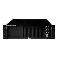
MP-2/4 Amplifier
Doc #: 05.033.040.01
Rev.: A
Date: 08/31/98
Page: 16 of 26
© 1998 Meyer Sound Laboratories, Inc. All rights reserved.
7. Remove the eight (8) small head screws from the user panel.
8. While slowly removing the user panel, disconnect the audio signal cable from the input
board on the user panel by disengaging the locking gray connector. Also disconnect the AC
input connector (4 wire green connector) from the AC mains board.
9. Remove the sense cable (gray ribbon cable) and the transformer primary connector (8 wire
green connector) from the AC mains board.
10. While firmly holding the AC mains board, remove the three (3) screws on the top of the
chassis and remove the board.
11. Disconnect the white DC power harness from the Power supply module.
Caution: Be careful not to overflex the circuit board when removing the power harness connector.
12. Lay the unit on either side and remove the six (6) screws from the bottom of the amp
chassis.
13. Return the unit to the upright position and disconnect the audio signal cable from the
bottom Control board by unlocking the gray connector.
14. Remove the green four (4) pin male connector mounted on the edge of the amplifier
chassis.
Note: Two (2) nuts with lock washers secure the two (2) screws. Make sure to remove these nuts from
the chassis.
15. Lift up the bottom Amp/heatsink module in order to remove the white DC power
harness from the connector on the Amp/heatsink module. Disconnect the power harness
from the Amp/heatsink module.
Note: As you are lifting the Amp/heatsink module, thread the white DC power harness through
the chassis towards the Amp/heatsink module. This will allow you to lift the module clear of the amp
chassis.
16. Remove the bottom Amp/heatsink module, taking care to not disturb the position of the
fans. Do not remove the Control board from the Amp/heatsink module at this time.
17. Position the AC mains board inside the chassis and replace the three (3) screws into the
top of the chassis to reattach the AC mains board bracket.
18. Connect the sense cable and the transformer primary cable. Also replace the user panel.