'
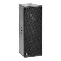
For a high power, compact system, we recommend using
two UPA-2Ps and two USW-1Ps. This array provides
< 143 dB SPL across 60° of horizontal coverage
Loading
As a general rule, if subwoofers are located in half-space
(single boundary, like a floor), then they have 6 dB more
gain than in free-field conditions.
This increase in low frequency energy is ideal for many
musical styles and venues but in some circumstances,
where a flatter response is desired we offer the following
solutions:
The VX-1:
The VX-1 is an ideal control option for a UPA-P and
USW-1P system. The VX-1 is a stereo virtual crossover
which allows the user to adjust the gain, switch between
stereo and mono distribution of two inputs and make
shelving EQ adjustments to the left and right sides of the
system.
Separate Feeds:
One simple method of attenuating the USW-1P is to feed
sperate signals to the USW-1P(s) and to the UPA-P(s).
With independent control of the main outputs and sub
levels, their relative proportions can be adjusted.
The Looping, Polarity, and Attenuating
Audio Input Module:
This optional module, described on page 6 of this user
guide allows for level control on the user panel of the
UPA.
Verifying Driver Polarity
Incorrect driver polarity impairs system performance and
may damage the drivers. All Meyer loudspeakers are
shipped with the drivers in correct alignment.
If the driver or circuit wiring has been removed or disas-
sembled it is essential to check the polarity between driv-
ers and between adjacent loudspeakers.
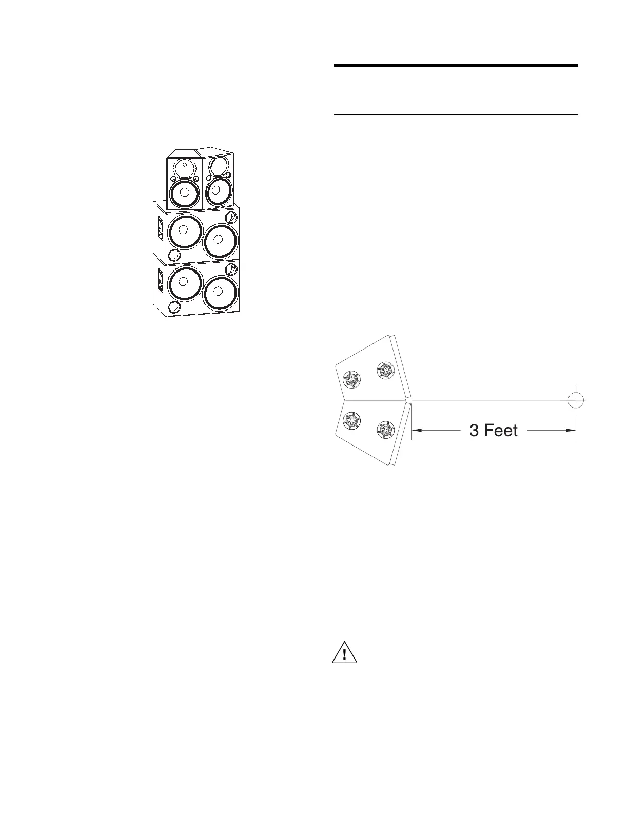
Polarity In Adjacent Loudspeakers
Use the following test procedure to verify the polarity
between two adjacent loudspeakers of the same type:
1. Position two loudspeakers adjacent to each other.
2. Place a measurement microphone 3 ft from the speak-
ers on the axis to the center of the array.
3. Connect a signal source to one speaker and note the
frequency response and overall level.
4. Apply the same signal to the second speaker with
the first speaker still connected.
The polarity is correct if the frequency response remains
constant with a 5-6 dB SPL increase in amplitude. Broad-
band cancellation (decreased overall level) indicates po-
larity reversal.
Since polarity reversal causes excessive driver
excursion at high source levels, use moderate
levels when conducting these tests.

 Loading...