41
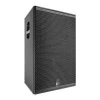
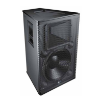
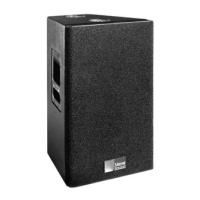
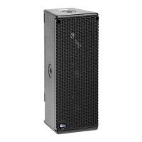
APPENDIX C: UPQ-D SERIES SPECIFICATIONS
UPQ-D SERIES ACOUSTICAL, ELECTRICAL, AND PHYSICAL SPECIFICATIONS
ACOUSTICAL
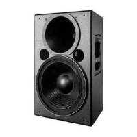
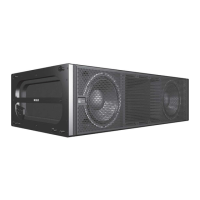
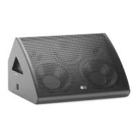
UPQ-D1 UPQ-D2 UPQ-D3
Operating Frequency
Range
55 Hz – 18 kHz 55 Hz – 18 kHz 55 Hz – 18 kHz
Note: Recommended maximum operating frequency range. Response depends on loading conditions and room
acoustics.
Frequency Response 58 Hz – 18 kHz ±4 dB 61 Hz – 16.5 kHz ±4 dB 57 Hz – 18 kHz ±4 dB
Note: Measured free field with 1/3 octave frequency resolution at 4 meters.
Phase Response 80 Hz to 18 kHz ±45° 80 Hz to 18 kHz ±45° 80 Hz to 18 kHz ±45°
Linear Peak SPL 135.5 dB with crest factor >17 dB
(M-noise), 132 dB (Pink Noise), 135
dB (B-noise)
138 dB with 19 dB crest factor
(M-noise), 134.5 dB (Pink Noise),
137 dB (B-noise)
135 dB with crest factor >17 dB
(M-noise), 132 dB (Pink Noise),
134 dB (B-noise)
Note: Linear Peak SPL is measured in free-field at 4 m referred to 1 m. Loudspeaker SPL compression measured
with M-noise at the onset of limiting, 2-hour duration, and 50-degree C ambient temperature is < 2 dB.
M-noise is a full bandwidth (10 Hz–22.5 kHz) test signal developed by Meyer Sound to better measure the loud-
speaker’s music performance. It has a constant instantaneous peak level in octave bands, a crest factor that
increases with frequency, and a full bandwidth Peak to RMS ratio of 18 dB. The presence of a greater-than (>) sym-
bol with regard to crest factor indicates it may be higher depending on EQ and boundary loading.
Pink noise is a full bandwidth test signal with Peak to RMS ratio of 12.5 dB.
B-noise is a Meyer Sound test signal used to ensure measurements reflect system behavior when reproducing the
most common input spectrum, and to verify there is still headroom over pink noise.
Coverage 80° H x 50° V (–6 dB)
100° H x 60° V (–10 dB)
50° x 50° (–6 dB)
60° x 60° (–10 dB)
80° x 80° (–6 dB)
100° x 100° (–10 dB)
TRANSDUCERS
Low Frequency One high-power 15-inch cone driver; 2 :nominal impedance
High Frequency One 4-inch diaphragm compression driver; 8 :nominal impedance
AUDIO INPUT
Type Differential, electro nically balanced
Maximum Common
Mode Range
±15 V DC, clamped to earth for voltage transient protection
Connectors XLR 3-pin female input with male loop output; optional XLR 5-pin connector to accommodate both balanced audio
and RMS signals.
Input Impedance 10 k: differential between pins 2 and 3
Wiring Pin 1: Chassis/earth through 1 k:, 1000 pF, 15 V clamp network to provide virtual ground lift at audio frequencies
Pin 2: Signal +
Pin 3: Signal – (optional polarity reversal switch)
Case: Earth ground and chassis
Note: Pins 4 and 5 (RMS) only included with XLR 5-pin connector that accommodates both balanced audio and
RMS signals.
Nominal Input Sensitivity 0 dBV (1 V rms) continuous average is typically the onset of limiting for noise and music
Input Level Audio source must be capable of producing +20 dBV (10 V rms) into 600 :to produce maximum peak SPL over the
operating bandwidth of the loudspeaker
 Loading...