The MFJ-9219 is a compact and robust QRP Tuner, Wattmeter, and Dummy Load, designed for both novice and experienced QRP (low-power) radio operators. It combines the functionalities of an antenna tuner, SWR/wattmeter, and a dummy load into a single, portable unit.
Function Description
The primary function of the MFJ-9219 is to match the impedance of a radio's transmitter to an antenna, ensuring efficient power transfer and minimizing Standing Wave Ratio (SWR). It achieves this through a T-network tuner. The device also incorporates a multipurpose meter that can display either SWR or power output, and an internal 20W dummy load for testing and tuning without radiating a signal.
Important Technical Specifications
- Dimensions: 5 x 4 1/4 x 2 1/2 inches
- Weight: 51 oz
- Power Handling: Up to 20W for the internal dummy load/wattmeter, and up to 100W in BYPASS mode (for the tuner).
- Tuner Type: T-network
- Meter: Multipurpose meter displaying SWR or power (unitless 1-5 scale).
- Frequency Range: The manual mentions 160m band (1.8 MHz) and 2-meter VHF (145 MHz) in the context of electromagnetic waves, implying a broad operational frequency range for the tuner, consistent with general amateur radio bands. The electromagnetic spectrum discussion covers 3 kHz to 300 GHz.
- Internal Load: 20W resistive dummy load.
- Power Source: The unit does not require external DC power.
Usage Features
The MFJ-9219 offers several user-friendly features:
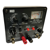
- Multipurpose Meter (1): This meter is central to operation, displaying either SWR or power levels. The power display is on a 1-5 scale, requiring a scaling factor (e.g., 4W per unit for a 20W maximum) to determine actual power.
- SWR Circuit BYPASS Switch (2): Allows bypassing the SWR metering circuit when not needed.
- SWR/PWR Switch (3): Toggles the meter between SWR and wattmeter modes. Engaging the wattmeter mode simultaneously activates the internal 20W dummy load.
- METER SENSITIVITY Knob (4): Adjusts the sensitivity of the multipurpose meter, allowing users to set the needle to full power (5) during calibration for accurate SWR readings.
- RADIO Connection (5): Standard connection point for the radio's output.
- ANTENNA Connection (6): Standard connection point for the antenna.
- INDUCTANCE Control (7): A multi-position switch that adjusts the inductance in the tuner circuit. This is a critical control for achieving a low SWR.
- Tuner BYPASS Control (8): Bypasses the entire tuner circuit, allowing direct connection between the radio and antenna. This is useful when an antenna is already matched or for operating at higher power levels (up to 100W).
- ANTENNA and TRANSMITTER Controls (9): These knobs adjust the capacitance for the antenna and transmitter sides of the T-network tuner, working in conjunction with the INDUCTANCE control to achieve an optimal match.
System Setup:
The setup is straightforward, requiring only connections between the radio and the MFJ-9219's RADIO port, and the antenna to the MFJ-9219's ANTENNA port. No external power is needed.
Operation Stages:
- SWR/Wattmeter Setup:
- Bypass the tuner (Switch 8) and set the SWR/Wattmeter to TUNE (Switch 2).
- Set the SWR/PWR switch (Switch 3) to PWR.
- Transmit at the desired power (<20W) and adjust the METER SENSITIVITY knob (4) until the meter reads full power (5).
- Switch the SWR/PWR switch (3) to SWR.
- Tuner Engagement:
- Engage the tuner (Switch 8).
- Set TRANSMITTER control (9) to 5 and ANTENNA control (9) to 0.
- Apply enough RF power to get a meter deflection.
- Adjust INDUCTANCE control (7) to find the lowest SWR.
- Slowly adjust TRANSMITTER (9) and ANTENNA (9) controls, iteratively, to find the lowest SWR.
- Refine the SWR by reducing inductance one switch position at a time with the INDUCTANCE control (7), then readjusting TRANSMITTER (9) and ANTENNA (9) for the lowest SWR. Repeat until the lowest SWR cannot be further reduced.
- Increase inductance by one switch position with the INDUCTANCE control (7) and tune for the lowest SWR.
- Set the SWR/Wattmeter to bypass.
Maintenance Features
- Thermal Warning: Due to the small size of the internal resistors, the unit can heat up significantly, especially when using the dummy load or wattmeter at higher power levels.
- Above 5W, transmit time in SWR, Wattmeter, and Dummy Load modes should be limited to less than 10 seconds.
- Allow 2 to 5 minutes for resistors to cool between transmissions at higher power.
- It is recommended to keep power below 100W in BYPASS mode.
- Never transmit while adjusting the INDUCTANCE switch.
The MFJ-9219 is designed for portability and ease of use, making it an excellent choice for QRP enthusiasts who need a versatile and reliable tool for antenna tuning and power management in the field or at home. Its robust construction and comprehensive features ensure it can handle the demands of various operating conditions.