MFJ-9219 QRP Tuner, Wattmeter, & Dummy Load Instruction & Technical Manual
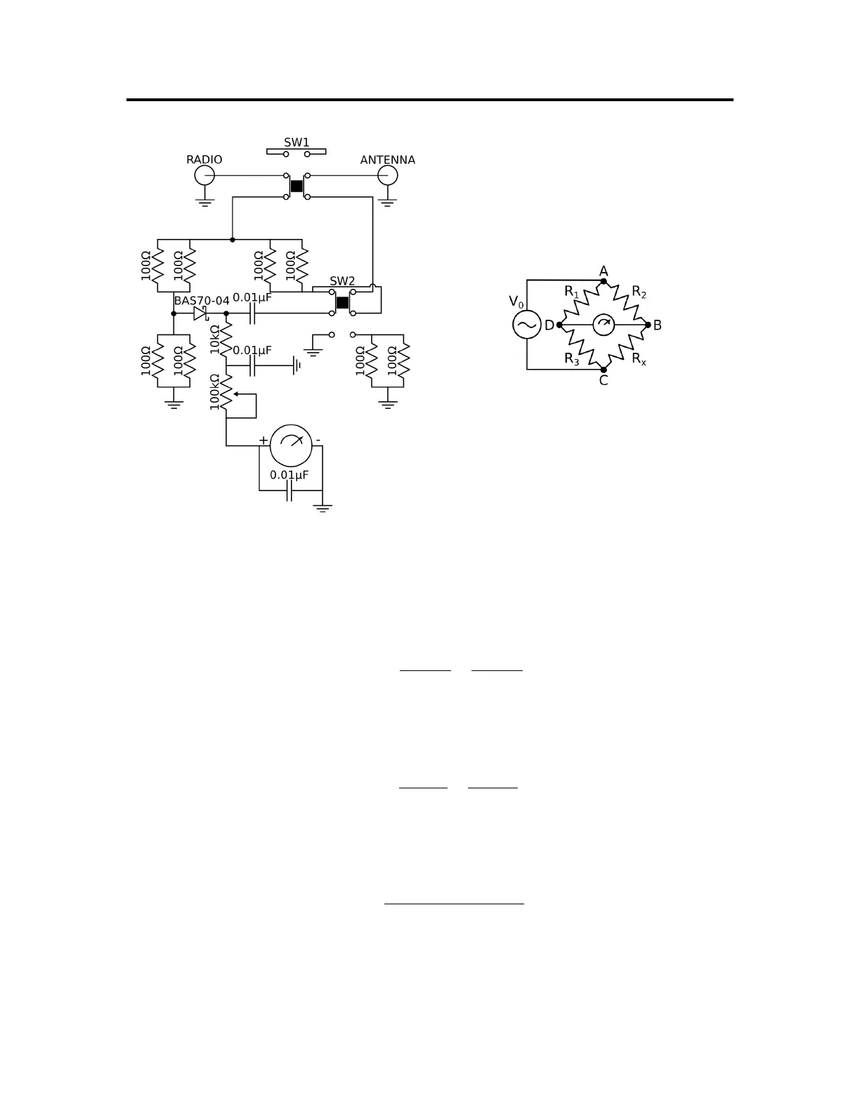
(a) MFJ-9219 Partial Circuit Schematic (b) A Wheatstone Bridge
Figure 4: Relevant Schematics
is sufficiently large that I
BD
is negligible (reasonable for most meters and the MFJ-9219), V
BD
can
be written in terms of the source potential V
0
and the resistances. This is shown in Equation 1.
V
BD
= V
0
R
2
R
1
+ R
2
−
R
x
R
x
+ R
3
(1)
Finally, if we extend our source to include AC (or RF) potentials and replace R
x
with a load, such
as an antenna, we can write Equation 1 in terms of reactances to get
V
BD
= V
0
Z
2
Z
1
+ Z
2
−
Z
x
Z
x
+ Z
3
. (2)
Resistors will have negligible reactances, so Z
1
, Z
2
, and Z
3
will only carry their resistances of 50Ω.
This converts Equation 2 into
Z
x
= R
3
V
0
R
2
− V
BD
(R
1
+ R
1
)
V
0
R
1
+ V
BD
(R
1
+ R
2
)
. (3)
Now that we know the impedance in terms of known quatities (R
1
= R
2
= R
3
= 50Ω, V
BD
is
measured by the meter, and V
0
is “programmed in” during SWR calibration), we can determine
the SWR using Equation 4.
-4-