MFJ-941EK Tuner Kit Instruction Manual
- 12 -
CONSTRUCTION
Find the following coax connector items:
(4) SO-239 female chassis-mount coaxial connector
(8) 4-40 x 3/8" Machine Screw
(8) 4-40 Hex Nut, KEP (nuts with lock washers)
[ ] Install a connector at COAX 1 and tighten hardware.
[ ] Install a connector at COAX 2 and tighten hardware.
[ ] install a connector at TRANSMITTER and tighter hardware.
[ ] Install a connector at DUMMY LOAD and tighten hardware.
On the pc board, locate the free end of each of the following wires and route
them to the designated connectors.
[ ] Route COAX1 buss wire to COAX 1 connector, trim, install, and solder.
[ ] Route COAX2 buss wire to COAX 2 connector, trim, install, and solder.
[ ] Route T2 buss wire to TRANSMITTER connector, trim, install, and solder.
[ ] Route D/L buss wire to DUMMY LOAD connector, trim, install, and solder.
Find the following Ground Post items:
(1) 10-32 x 3/4" Machine Screw, PHH
(1) 10-32 Hex Nut, KEP
(1) 10-32 Wing Nut
(1) #10 Solder Lug
(2) #10 Flat Washer
(1) #10 Split Lock Washer
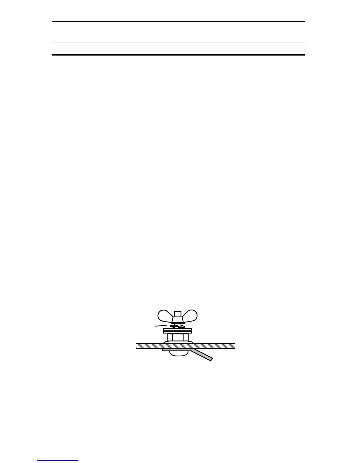
Locate the ground-post hole (GND) on the rear panel. Refer to Diagram 6.
Screw
Solder Lug
KEP Nut
Flat Washer (2)
Split Lockwasher
Wingnut
Groundpost Detail
Diagram 6: Groundpost Mounting
[ ] Install the solder lug on the screw and insert it out through back panel.
[ ] Install the KEP nut and tighten in place securely.
[ ] Install two flat washers