MFJ-941EK Tuner Kit Instruction Manual
- 8 -
CONSTRUCTION
[ ] Install 220 pF at C5 and solder.
[ ] Install .01 uF at C6 and solder.
[ ] Install .01 uF at C7 and solder.
Find the 3-10 pF trimmer capacitor (white ceramic, ~1/2" OD, 3 pins).
[ ] Install at C4 and solder.
On the pc board, locate the legend marking for C12 (next to trimpot R5).
[ ] Form a 1/4" jumper using a clipped-off lead end. Install at C12 and solder.
Find the 680-uH RF choke (blue, gray, brown).
[ ] Install 680-uH at L2 and solder.
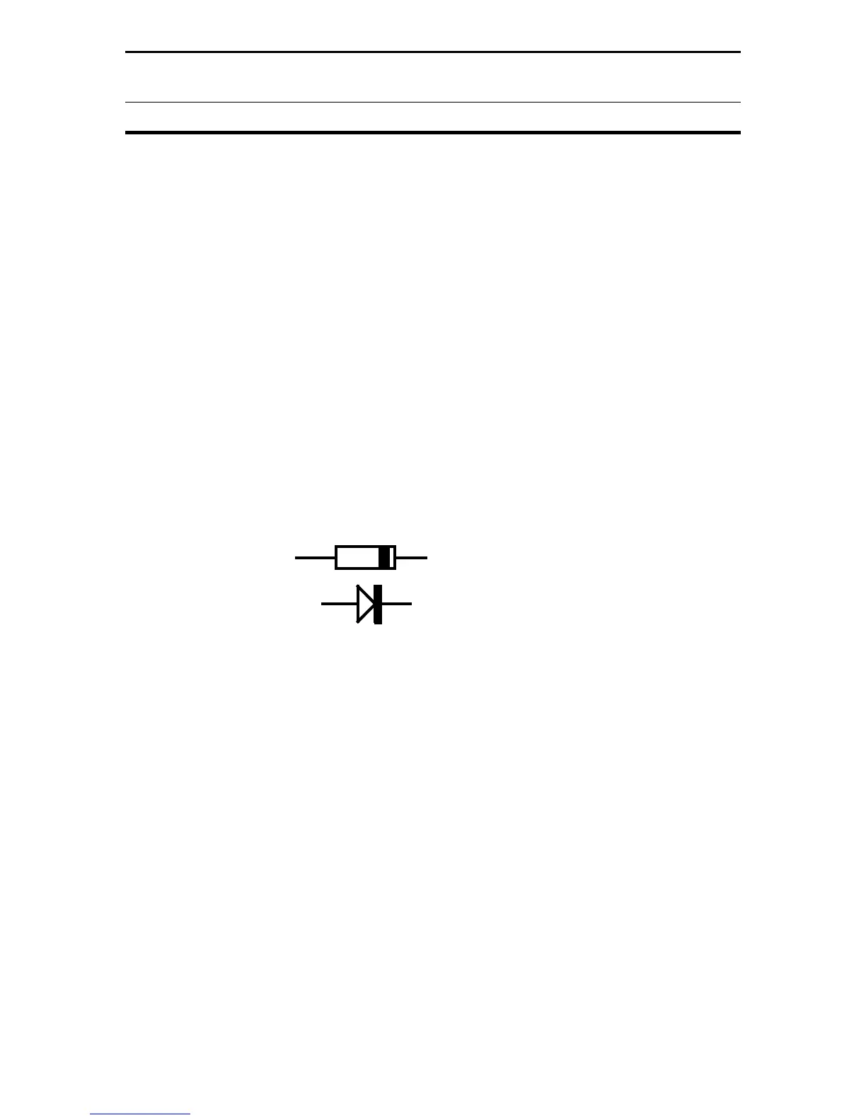
Find two (2) Schottky diodes, CDSH 270 (blue) and identify the banded end.
Refer to Diagram 1.
Cathode End
Diagram 1: Diode Orientation
[ ] Install a diode at D1 with the banded end (cathode) toward the D1 legend.
[ ] Install the second diode at D2 with banded end toward the D2 legend.
Find the following items:
(1) Switch, DPDT, push-on/push-off (6 pins)
(1) Switch, 4PDT, push-on/push-off (12 pins)
(1) 2.1-mm PCB power jack
[ ] Install the DPDT switch at SW1. Confirm all pins are fully seated, and solder.
[ ] Install the 4PDT switch at SW2. Seat pins, and solder.
[ ] Install the 2.1-mm power jack at J1 and solder.
Find the 8PDT pc-mount 2-section rotary switch (from the larger parts bag)
[ ] Orient the switch over the pc-board legend at SW4 and install.
[ ] Confirm all pins are firmly seated and solder.