MFJ-974/974H Balanced Line Antenna Tuner Instruction Manual
3
Installation
1. Place the tuner in a convenient location at the operating position. With random wire or balanced feedlines,
the feed through insulators may have high RF voltages. These voltages can cause serious RF burns if the
terminals are touched when transmitting. Be sure to locate the tuner so these terminals cannot
accidentally be contacted during operation.
2. Install the tuner between the transmitter and the antenna. Use a 50-ohm coaxial cable (such as RG-8/U) to
connect the transmitter to the connector marked TRANSMITTER on the rear of the tuner.
3. Connect the antenna feedline to the tuner as follows:
A. Coaxial feedlines connect to the coax connector labeled ANTENNA (a jumper wire is required between
the lower, red binding post and the ground terminal).
B. Random wire or single wire line antennas should be connected to the top red connector on the back of
the unit (jumper wire required between the lower, red binding post and the ground terminal).
Note
: Route all single and random wire antennas safely to prevent RF burn hazard.
C. Balanced feedline (open wire, twinlead, or twin-axial line) is connected to the BALANCED LINE
terminals.
4. A ground post is provided for an RF ground connection.
Operation
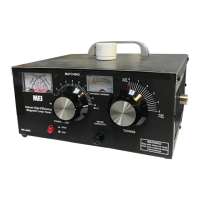
The MFJ-974H uses three inductors for maximum efficiency. A 2½-inch diameter high-Q air-wound inductor is
tapped for flexibility and is used on frequencies from 3.5 to 30 MHz. For 160 Meters (MFJ-974H only) an
additional inductance, made of Teflon™ insulated wire wound on two powdered-iron cores, is switched in by the
front panel 160 METER pushbutton. Front panel inductor switch position L automatically selects a 6-Meter only
inductance (bypassing the larger air-wound coil). Inductance switch position A is the greatest inductance,
position L the least. The inductance decreases as the knob is rotated clockwise.
The ANTENNA and TRANSMITTER capacitors have maximum capacitance at setting 0 and minimum
capacitance at setting 10.
Maximum tuner efficiency is achieved with the most capacitance (settings closest to 0) and the least possible
inductance (higher letters of the alphabet). This efficiency translates into best power handling, broadest
bandwidth, and least power loss. The goal is always to operate the tuner at the lowest Q for the LC
(inductance/capacitance) circuit.
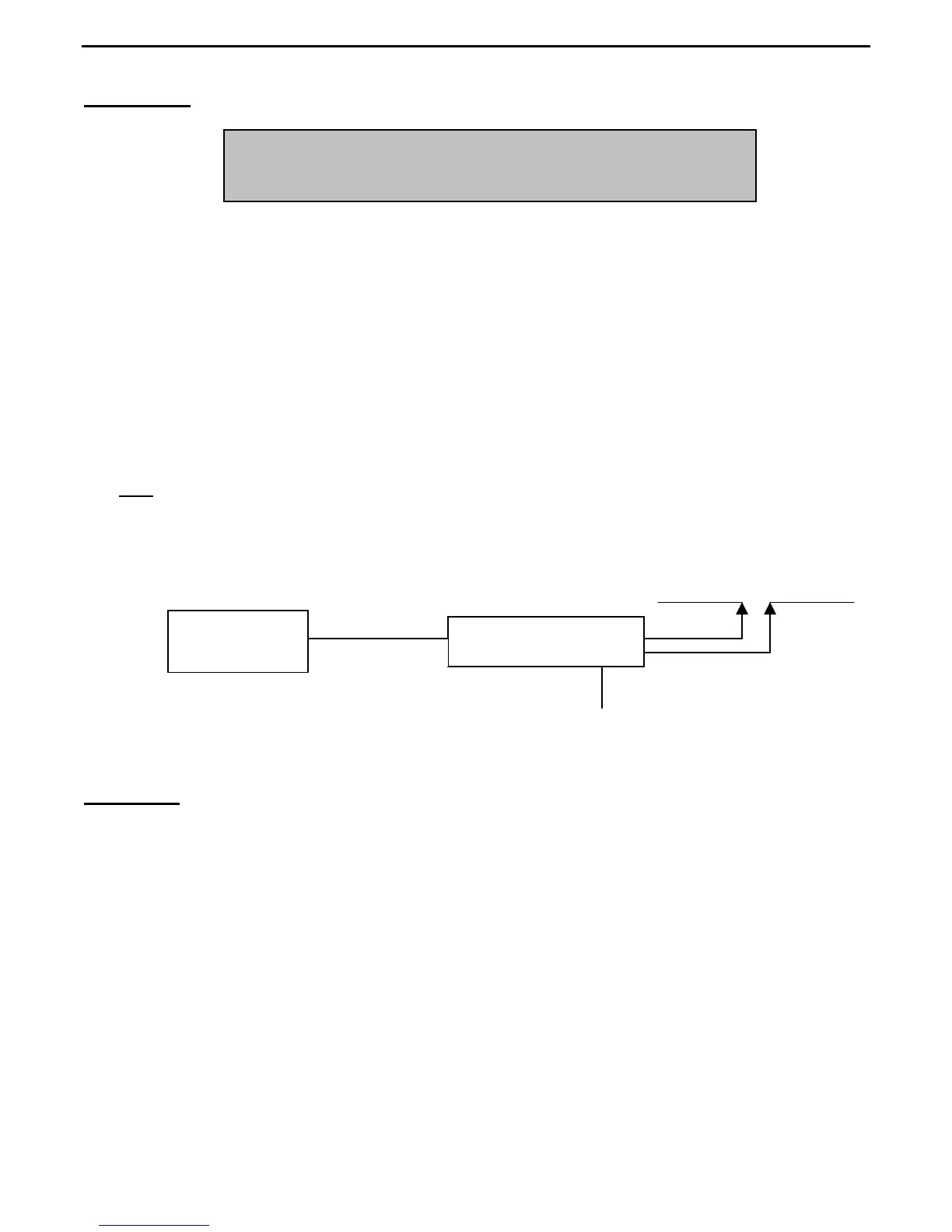
Transceiver or
Transmitter
MFJ-974H/974
-
RF ground
CAUTION
Locate the tuner so the rear is not accessible durin
o
eration.
Figure 1
Block Diagram