MFJ-974/974H Balanced Line Antenna Tuner Instruction Manual
4
When necessary to increase the tuner’s matching range, set the ANTENNA or TRANSMITTER control to a
higher number, or dial in a lower letter on the INDUCTOR switch, but remember that this lowers the efficiency
and power handling capability of the tuner.
Adjustment Procedure
1. If the exciter or transmitter must be tuned, do it into a 50-ohm dummy load.
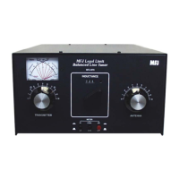
2. Set the ANTENNA, INDUCTANCE, and TRANSMITTER controls at the settings in the Suggested
Tuning Chart on Page 9. At these settings signals (or at least some noise) should be audible in your
receiver.
3. Place the POWER switch in the LO position.
4. Transmit at low power (20 or 25 watts should suffice).
5. Rotate the ANTENNA and TRANSMITTER controls for maximum forward power and minimum
reflected power (ideal). If full forward power and zero reflected power cannot be obtained, turn the
INDUCTOR one letter lower in the alphabet and try again. If this does not achieve a match, turn the
INDUCTOR control two letters lower and try.
Note
: Never change the INDUCTOR setting while power is applied to the tuner!
6. Once full forward power and zero reflected power are achieved, always try advancing the INDUCTOR
setting by one letter (higher) and tune for a match. If a match can be achieved at two different
INDUCTOR settings, the “higher letter” (lower inductance) setting is better.
7. Adjust transmitter to full output and touch up the tuner settings if needed.
8. For quick retuning of the tuner, record the INDUCTOR and CAPACITOR settings for each band (see
the Logged Tuning Chart, Page 10).
Note
: Maximum power handling is achieved when both the ANTENNA and TRANSMITTER
controls are set at the lowest possible number, and the INDUCTOR control is set at the highest possible
letter that permits matching the antenna. Following this guideline will ensure maximum power handling
capability and efficiency, and the smoothest tuning.
Operating Notes
While this tuner is designed to have as large a tuning range as possible, there are limits to the tuning range of the
capacitors. Some antennas may require more or less capacitance than is available. In these cases, the SWR may
not be reduced to 1:1. If the SWR is higher than the limits of your rig, try changing the length of the antenna or
feedline to bring the impedance within the tuning range of the tuner.
WARNING:
• Never operate the tuner with the top removed. Contact with the components
inside the tuner while transmitting will result in painful RF burns.
• Never rotate the INDUCTANCE switch while transmitting. Doing so may
permanently damage the switch.
• Locate the tuner so that the rear terminals are not accessible during operation.
The balanced line connectors may have high voltage on them while transmitting.
• Disconnect all antennas from the tuner during lightning storms.
• Always tune with low power (i.e. less than 100 watts). Apply maximum power
only after tuning up.
• Be sure to adjust the SWR before transmitting at full power. Do not transmit
with a high SWR for extended periods.