MFJ-962E Instruction Manual
5
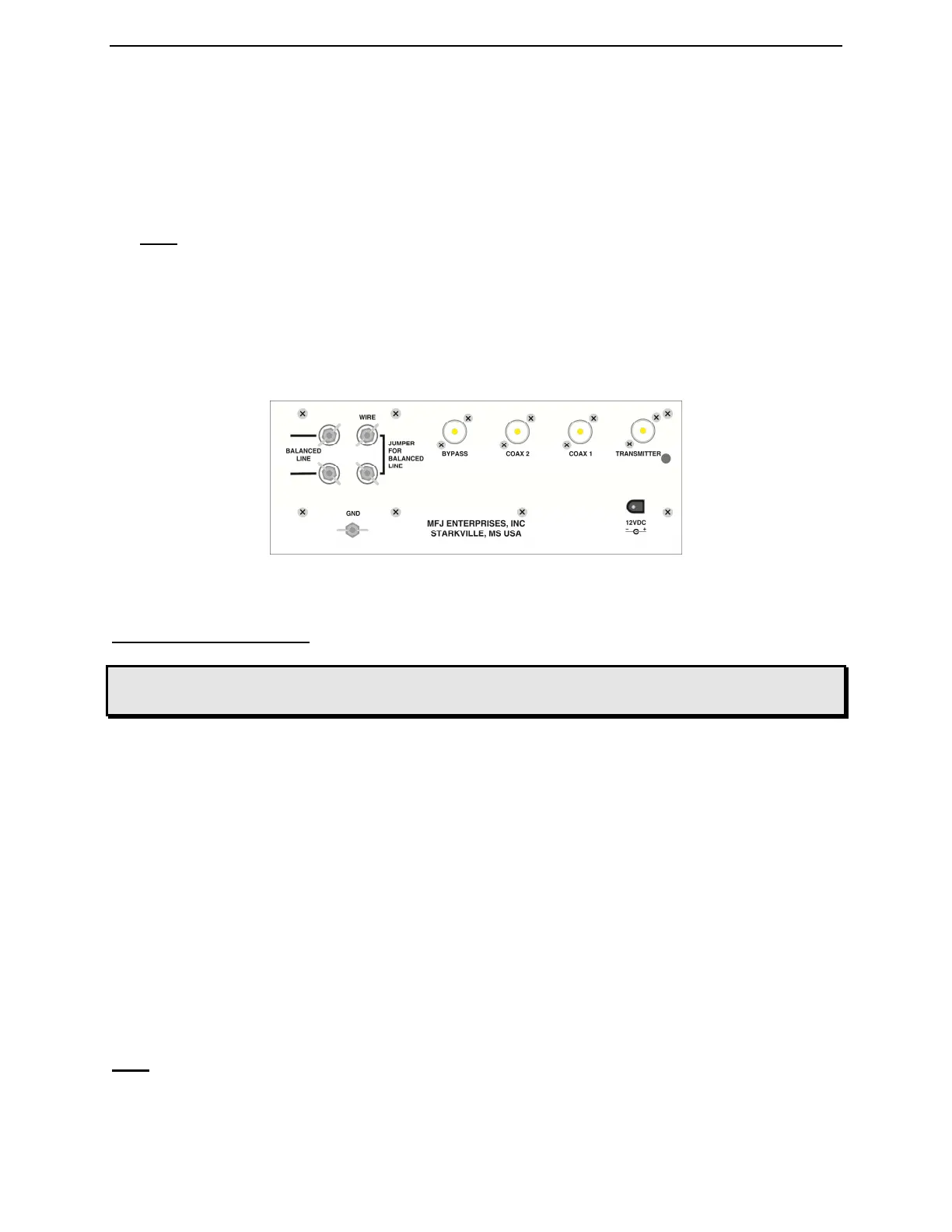
A. Coaxial feedlines connect to the coax connectors 1 and 2 coax line (fed direct or through
matching circuit as selected by the ANTENNA SELECTOR switch).
B. Random wire or single wire line antennas should be connected to the WIRE terminal.
Note: Route all single and random wire antennas to prevent RF burn hazard.
C. Any balanced feedline (open wire, twinlead, or twin-axial lines) is connected to the
BALANCED LINE terminals. Connect a jumper between the WIRE terminal and the
terminal below it to enable the balanced line terminals.
4. A ground post is provided for an RF ground connection.
Back Layout
Figure 2
Using The MFJ-962E
WARNING: Never change the Antenna Selector position while transmitting!
Never apply more than 800 Watts to the MFJ-962E !
In any conventional "T" network tuner, maximum power handling and the smoothest tuning
occurs when the capacitance in the network is as large as possible. In this tuner the
TRANSMITTER and ANTENNA MATCHING controls have maximum capacitance at
position 0 (fully meshed), and minimum capacitance at position 10 (fully open). Be sure to use
the highest possible capacitance for each band. This will provide the smoothest tuning, highest
efficiency, and greatest power handling capability.
The roller inductor has a minimun inductance when the knob is rotated fully clockwise and the
counter displays approximately "125". When the roller is rotated fully counter-clockwise, it has
maximum inductance and the counter display is set at "000". If the counter is not set a "000"
when the roller is rotated fully counter-clockwise, reset the counter to "000". Reset the counter
by using a small screwdriver or a pencil and push the reset lever through the hole beside the
counter.
Note: If your transmitter uses an adjustable output circuit, it must be properly tuned into a 50
ohm load at the operating frequency. Proper tuning can be accomplished by placing the
ANTENNA SELECTOR switch in the fully clockwise COAX BYPASS position with a