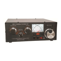
MFJ-962E Instruction Manual
4
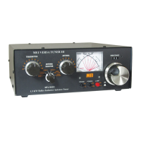
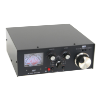
The reflected power is read on the right-hand REFLECTED meter scale. This scale indicates 60
watts full scale when the 300W power sensitivity is selected, and 600 watts full scale when the
3000W power scale is selected. This scale has a picket every watt below 10 watts and every 5
watts above 10 watts. This scale is also multiplied by 10 when using the 3000W power position.
The most accurate power readings occur in the upper half of the meter scales. When trying to
measure power with a less than perfect match, the reflected power should be subtracted from the
forward power readings.
The SWR is read directly from the nine red SWR curves that range from 1:1 to infinity. SWR is
measured by observing the point where the forward and reflected power needles cross. The SWR
is indicated by the red curve closest to the needle crossing point. No cumbersome or time
consuming SWR sensitivity adjustments are required with this meter.
The wattmeter has an internal lamp that backlights the meter scale. The METER LAMP ON /
OFF switch turns the meter lamp on and off. The antenna relay switching network and the peak
power circuit requires power from an external 12 VDC source, such as the optional MFJ-1312B
power supply. The rear panel jack accepts a 2.1 mm coaxial plug with the center conductor
positive (+) and the sleeve negative (-). The negative lead is grounded inside the tuner.
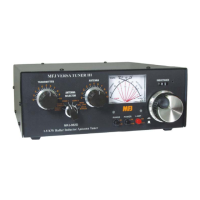
Antenna Selector
The ANTENNA SELECTOR allows you to select either of the 2 rear panel SO-239 antenna
coaxial connectors, direct or through the tuner, a coax bypass output, and balanced feedline or
wire antennas.
Installation
CAUTION: Locate the tuner so that the rear panel is not accessible during
operation.
1. Locate the tuner in a convenient location at the operating position. If balanced line or wire
line operation is used, the feed through insulators may have high RF voltages. These
voltages can cause serious RF burns if the terminals are touched when transmitting. Be sure
to locate the tuner so that these terminals can not be accidentally contacted during
operation.
2. Install the tuner between the transmitter and the antenna as shown in the diagram below. Use
a coaxial cable capable of handling the power (such as RG-8/U) to connect the transmitter (or
amplifier) and to the connector marked TRANSMITTER on the rear of the tuner.
3. Connect the antenna(s) to the tuner as follows:
The tuner or meters will not function without 12VDC.