R8-PC4A
EM-9795 Rev.4 P. 5 / 6
MG CO., LTD. www.mgco.jp
5-2-55 Minamitsumori, Nishinari-ku, Osaka 557-0063 JAPAN
TERMINAL CONNECTIONS
Connect the unit as in the diagram below.
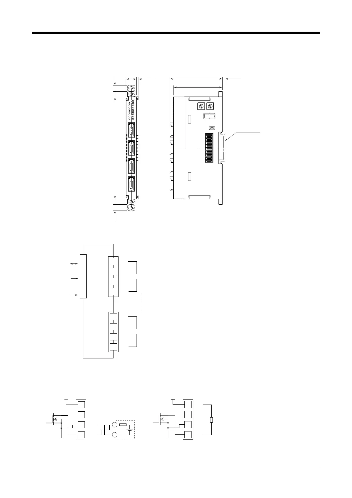
■ EXTERNAL DIMENSIONS unit: mm (inch)
115 (4.53)6 (.24)7 (.28) 6 (.24) 7 (.28)
DIN RAIL
(35 mm wide)
[3 (.12)]
[4 (.16)]
12 (.47)
59 (2.32)
55 (2.17)
■ CONNECTION DIAGRAM
24V
NC
0V
Po1
1
2
4
3
24V
NC
0V
Po4
1
2
4
3
OUTPUT
CONNECTOR 1
OUTPUT
CONNECTOR 4
OUTPUT 4
INTERNAL
BUS
EXC.
SUPPLY
BUS CONNECTOR
INTERNAL
POWER
Output Connection Examples
Note: Pin 1 of output connector is connected to 24V of the excitation supply.
Pin 1 of output connector is connected to 0V of the excitation supply.
■Open Collector
24V
NC
0V
Pon
1
2
4
3
+24V
0V
+
–
24V
NC
0V
Pon
1
2
4
3
+24V
0V
Po
■Wet Contact
OUTPUT 4