R8-PC4A
EM-9795 Rev.4 P. 3 / 6
MG CO., LTD. www.mgco.jp
5-2-55 Minamitsumori, Nishinari-ku, Osaka 557-0063 JAPAN
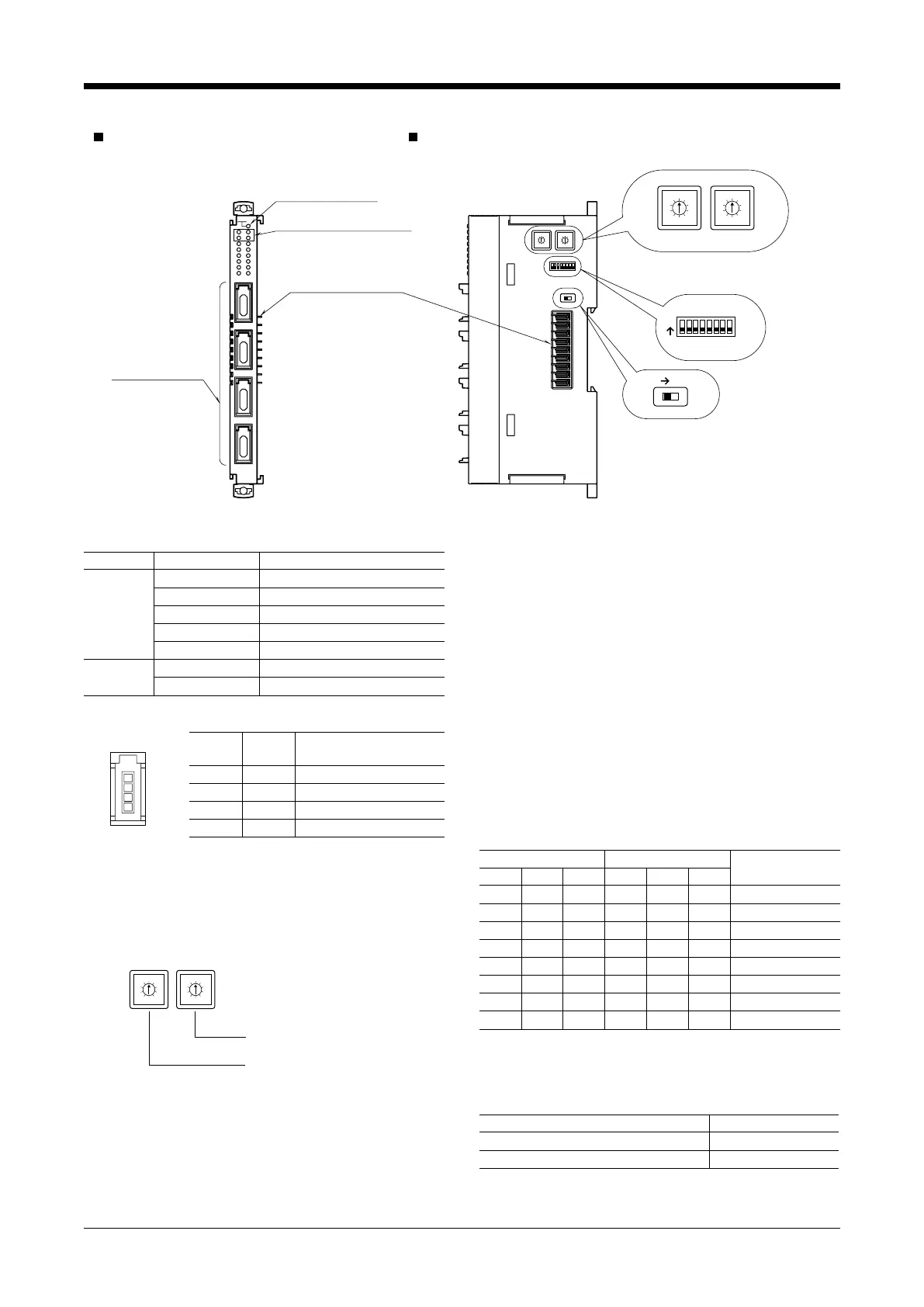
COMPONENT IDENTIFICATION
RUN
Module Address Setting
Rotary SW
Function Setting
DIP SW
Terminator DIP SW
5
4
3
2
1
0
9
8
7
6
5
4
3
2
1
0
9
8
7
6
SW1
x10
12345678
x1
SW2
SW4
SW3Term
On
On
Status Indicator LED
Output Status Indicator LED
Internal Bus Connector
Output Connectors
FRONT VIEW SIDE VIEW
CARD ADD.
PO1
PO2
PO3
PO4
5
4
3
2
1
0
9
8
7
6
5
4
3
2
1
0
9
8
7
6
■ INDICATOR LED
ID OPERATION FUNCTION
Status OFF Stopping
Green ON Valid host communication
Green Blinking Reading/writing configuration
Red ON Setting error
Red Blinking Parameter error
Output
Status
OFF OFF
Green ON ON
■ OUTPUT CONNECTOR ASSIGNMENT
1
2
3
4
PIN
No.
ID FUNCTION
1 24V 24V
2 NC No connection
3 NC No connection
4 PO Output
Note: Pin 1 is connected to the excitation supply.
■ MODULE ADDRESS: SW1, 2
The left switch determines the tenth place digit, while the
right one does the ones place digit of the module address.
Address is selected between 0 to 30.
(Factory setting: 0)
Module Address Setting (x10)
Module Address Setting (x1)
5
4
3
2
1
0
9
8
7
6
5
4
3
2
1
0
9
8
7
6
■ OPERATING MODE
(*) Factory setting
• Counter Reset: SW4-1
1) Turn the power off.
2) Turn ON the Counter Reset SW (SW4-1).
3) Return the module to the base and turn the power supply
ON. The status indicator LED turns ON in amber.
4) Wait at least 5 seconds. Turn the power supply OFF.
5) Turn OFF the Counter Reset SW (SW4-1).
6) Return the module to the base and turn the power supply
ON.
Note: Counter Reset SW must be turned OFF after this pro-
cedure because the module does not start counting with
ON state.
• ON/OFF Pulse Width: SW4-2, 3, 4, 5, 6, 7
Setting for all outputs.
Setting for each output can be done with a PC.
ON OFF PULSE WIDTH
TIME *
1
2 3 4 5 6 7
OFF OFF OFF OFF OFF OFF 5 msec.(*)
ON OFF OFF ON OFF OFF 10 msec.
OFF ON OFF OFF ON OFF 15 msec.
ON ON OFF ON ON OFF 100 msec.
OFF OFF ON OFF OFF ON 500 msec.
ON OFF ON ON OFF ON 1 sec.
OFF ON ON OFF ON ON 1.5 sec.
ON ON ON ON ON ON 2 sec.
*1. Minimum ensured time duration. For example, with 5
msec. setting, the minimum pulse width is 5 msec. (Max.
value = Setting time + 2 msec.)
• Conguration Mode: SW4-8
CONFIGURATION MODE SW4-8
DIP switch setting (*) OFF
PC Configurator and communication ON
 Loading...