EasyManua.ls Logo

MG Filter User Manual

MG Filter
6 pages
To Next Page IconTo Next Page
Page #1 background imageLoading...
Page #1 background image
EM-9795 Rev.4 P. 1 / 6
MG CO., LTD. www.mgco.jp
5-2-55 Minamitsumori, Nishinari-ku, Osaka 557-0063 JAPAN
INSTRUCTION MANUAL
BEFORE USE ....
Thank you for choosing us. Before use, please check con-
tents of the package you received as outlined below.
If you have any problems or questions with the product,
please contact our sales office or representatives.
PACKAGE INCLUDES:
Pulse output module ...........................................................(1)
MODEL NO.
Confirm Model No. marking on the product to be exactly
what you ordered.
INSTRUCTION MANUAL
This manual describes necessary points of caution when
you use this product, including installation, connection and
basic maintenance procedures.
POINTS OF CAUTION
CONFORMITY WITH EU DIRECTIVES
The equipment must be mounted inside a panel.
The actual installation environments such as panel con-
figurations, connected devices, connected wires, may af-
fect the protection level of this unit when it is integrated
in a panel system. The user may have to review the CE
requirements in regard to the whole system and employ
additional protective measures to ensure the CE conform-
ity.
GENERAL PRECAUTIONS
Before you remove or mount the unit, turn off the power
supply and output signal for safety.
Switches on the side of the module can be set for mainte-
nance only while the power supply is off. Do not access
them while the power is supplied.
ENVIRONMENT
Indoor use.
When heavy dust or metal particles are present in the
air, install the unit inside proper housing with sufficient
ventilation.
Do not install the unit where it is subjected to continuous
vibration. Do not subject the unit to physical impact.
Environmental temperature must be within -10 to +55°C
(14 to 131°F) with relative humidity within 30 to 90% RH
in order to ensure adequate life span and operation.
WIRING
Do not install cables close to noise sources (relay drive
cable, high frequency line, etc.).
Do not bind these cables together with those in which
noises are present. Do not install them in the same duct.
AND ....
The unit is designed to function as soon as power is sup-
plied, however, a warm up for 10 minutes is required for
satisfying complete performance described in the data
sheet.
INSTALLATION
HOW TO MOUNT THE MODULE ON DIN RAIL
A
B
• I/O Module
Confirm that the locking clamps of the I/O module are set.
Insert the module in parallel to the next one while aligning the grooves of
both modules (A & B in the above figure).
Maintain it perpendicularly to the rail.
More I/O modules can be added in the same manner.
PULSE OUTPUT MODULE
(NPN transistor output, 4 points, voltage contact)
MODEL
R8-PC4A
Question and Answer IconNeed help?

Do you have a question about the MG Filter and is the answer not in the manual?

MG Filter Specifications

General IconGeneral
BrandMG
ModelFilter
CategoryControl Unit
LanguageEnglish

Summary

Before Use and Initial Checks

Package Includes

Verify the contents of the package received, including the pulse output module.

Model Number Confirmation

Confirm the model number marking on the product matches the ordered item.

Points of Caution

EU Directives Conformity

Panel mounting, environment configuration, and CE conformity requirements for system integration.

General Precautions

Safety measures before removing/mounting, power off procedures, and switch access.

Environmental Considerations

Installation guidelines for dust, vibration, impact, and operating temperature/humidity.

Wiring Guidelines

Guidelines for routing cables away from noise sources and shared ducts.

Installation and Mounting

Mounting on DIN Rail

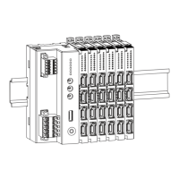
Instructions for attaching the I/O module to a DIN rail, including clamp confirmation.

Unmounting from DIN Rail

Procedure for safely removing the module from the DIN rail, releasing locking clamps.

Protective Cover Installation

Attaching the protective cover over the connected I/O module at the right end.

Removing Intermediate Module

Guidance on how to remove an intermediate module from the DIN rail assembly.

Component Identification and Settings

Front and Side View Identification

Identification of components like LEDs, connectors, and setting switches on the module.

Indicator LED Status

Explanation of indicator LED status (Stopping, Host Communication, Error) and their functions.

Output Connector Assignment

Details on the pin assignments for output connectors, including voltage and function.

Module Address Setting

Instructions for setting the module address using rotary switches (SW1, SW2).

Operating Modes and Settings

Configuration of operating modes like Counter Reset, Pulse Width, and Configuration Mode via DIP switches.

Advanced Settings and Operation

Terminator DIP Switch

Configuration of the terminator switch (SW3) for signal termination.

Pulse Output Operation

Explanation of how the R8-PC4A outputs pulses based on target and present values.

PC Configurator Parameters

Overview of parameters configurable via PC Configurator Software (R8CFG).

Channel Individual Setting

Configurable parameters for individual channels like max pulse count and ON/OFF times.

Channel Batch Setting

Batch settings for channels, including bus communication detection time.

Terminal Connections and Dimensions

External Dimensions

Physical dimensions of the R8-PC4A module in millimeters and inches.

Connection Diagram

Schematic showing internal bus, power, and output connector wiring.

Output Connection Examples

Illustrations of Open Collector and Wet Contact output connection types.

Wiring Instructions

e-CON Connector Specifications

Details on the unit side and recommended cable side e-CON connectors and applicable wire sizes.