We then see in Illustration No.
I6
the front end of the crankshaft after
the front end housing has been removed and the manner in which the shaft
is supported in
a
ball bearing. This illustr:~tion also shows the two keys on
the crankshaft on to which the two ge;~r wheels fit.
On looking
at
the front cnd housing c:ln also be seen the front bearing,
which is
a
ball race specialy designed to carry loads both in radial and thrust
direction, and can be renlovcd from the housing after taking out the four
fixing screws shown
in
Illustration No.
16.
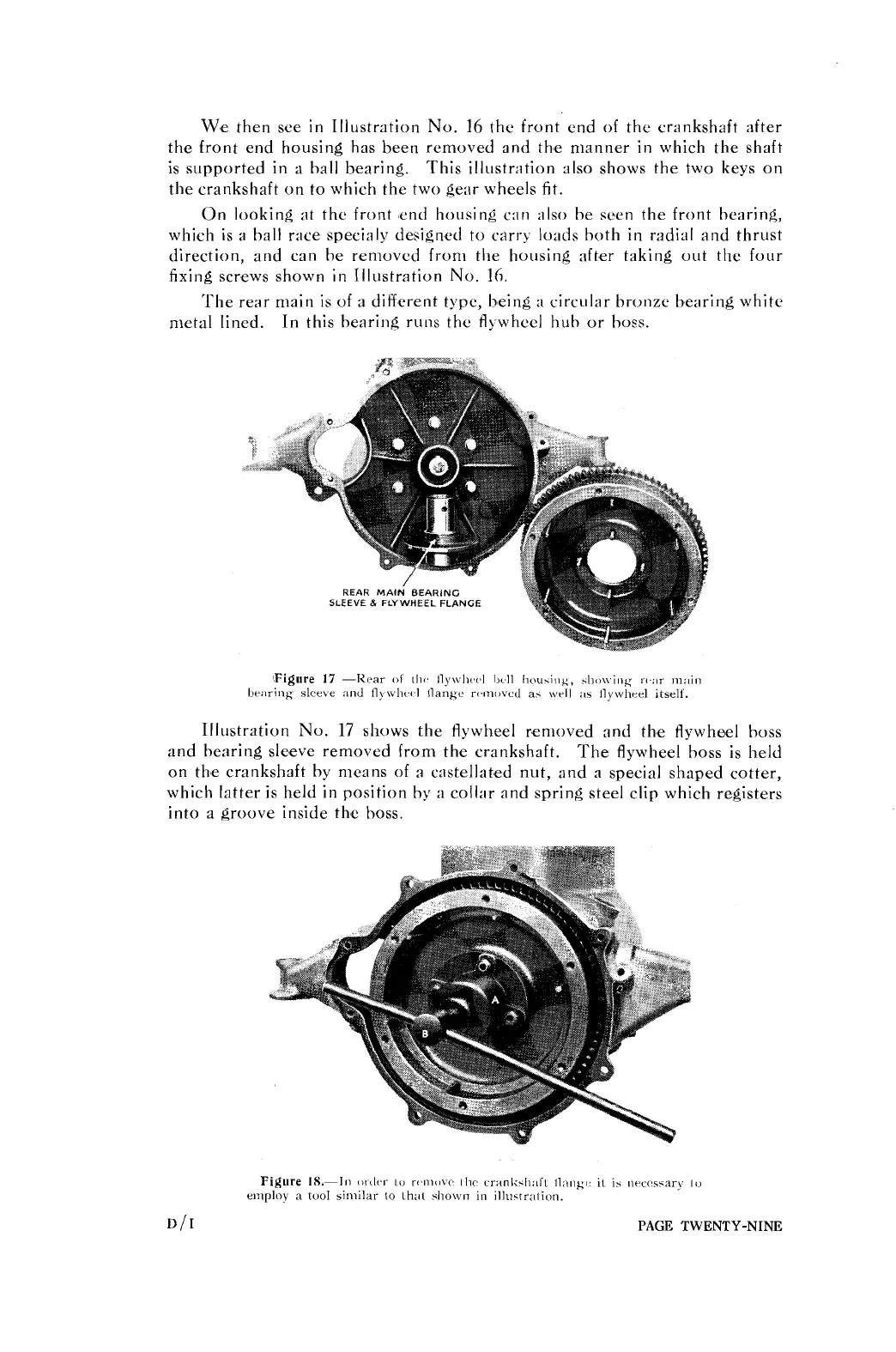
The rear main is of a different type, being
:I
circular bronze bearing white
metal lined.
In this bearing runs the
fl!
wheel hub or boss.
1llustr:ition No.
17
shows the flywheel removed and the flywheel
boss
and bearing sleeve removed from the crankshaft.
The flywheel boss is held
on the crankshaft by means of
a
castellated nut, and a special shaped cotter,
which latter is held in position by
a
collar and spring steel clip which registers
into a groove inside the boss.
PAGE TWENTY-NINE