In order to remove the crankshaft flange, it is necessary to employ a tool
similar to that shown in 1llustr:ltion No.
13.
Engine Lubication.
The engine sump holds one gallon of oil and is re-
plenished through an e:rsily accessible filler on the off side of the engine.
The
oil level in the sump is quickly ascertained by means of the
"
dip-stick,"
which is just behind the oil filkr; this has two marks on it, the upper one
showing the level with the sump full, while the lower one is the danger line.
To
take
a rcadill,~ the cnfiinc
sl~oul~l
b~
szitched
off;
the dip-stick is with-
drawn, wiped clean, reinserted to its full length, withdrawn again, and then
read. These precautions are necessary, as when the engine is running the oil
in the sump is churned up, and splashes on the dip-stick may give a flilse
reading.
The
oil
level should be inspected every day before starting out, or every
100-150
miles on a long tour, and although it need not always be absolutely
full, the level should he kept well up, especially when the car is new and
never allowed to fall lower than half-way between the
"
full
"
and
"
danger
"
marks. At the same time overfilling should he c:irefully avoided as this
causes the oiling up of the plugs.
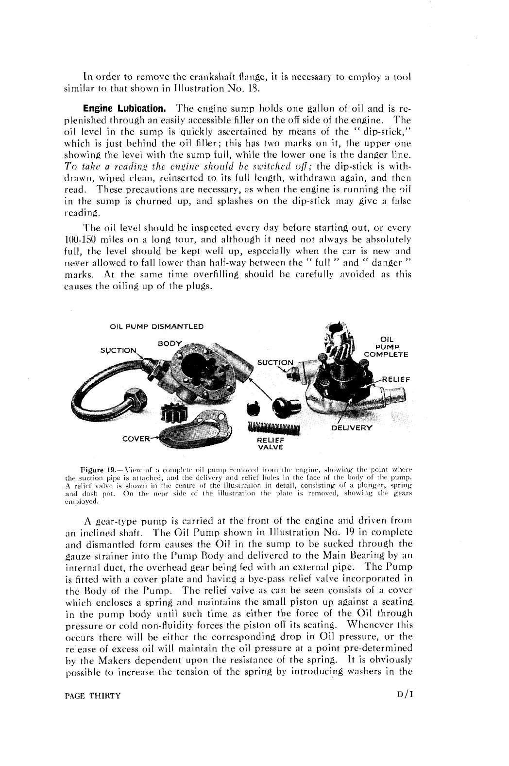
OIL
PUMP
DISMANTLED
Figure
19.-\.ir.\\. :I rornl)lr,c(. oil pump r(.rno\.(.d I'r,~m thc engine, sho\\,ing tlw point \vIic.r~-
the wction pipe
is
att:~chcd,
:~nd
thc delivery
and
relief holes in thc face
OS
thc body of thr pump.
A
relief valve
is
sho\vn in tlir crnlrr of thc illuslra~ion in detail, consisting
of
a
plunger,
spring
and dash
1x1~.
011
tlw ni3:Ir sidc of the illustration tlw
plate
is removed,
she\\-ing
~hr gl-arh
(.niploycd.
A
gear-type pump is carried at the front
of
the engine and driven from
an inclined shaft.
The
Oil
Pump shown in Illustration No.
19
in complete
and dismantled form causes the Oil in the sump to be sucked through the
gauze strainer into the
I'ump Rody and delivered to the Main Bearing by an
internal duct, the overhead gear being fed with an external pipe. The Pump
is fitted with
a
cover plate and having a bye-pass relief valve incorporated in
the Rody of the I'ump. Thc relief valve as can he seen consists of a cover
which encloses a spring and maintains the small piston up against a seating
in the pump
body until such time as eithser the force of the Oil through
pressure or cold non-fluidity forces the piston off its seating.
Whenever this
occurs there will be either the corresponding drop in
Oil
pressure, or the
release of excess oil will maintain the oil pressure at a point pre-determined
by the Makers dependent upon the resistance of the spring.
It is
obviously
possible
to
increase the tension of the spring by introducing washers in the
PAGE
THIRTY
D/I