employed to describe the Clutch plirts hy different people, but in this Works
they are described as follows
:
-
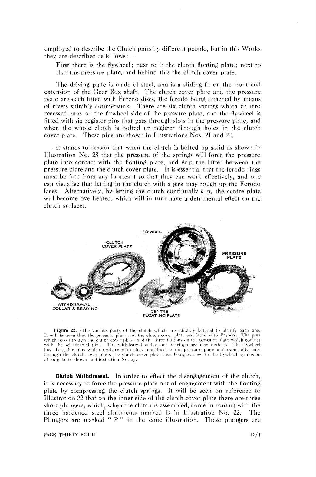
First there is the flywheel; nest to it the clutch floating plate; next to
that the pressure plate, and behind this the clutch cover plate.
Th'e driving plate is made of steel, and is
a
sliding fit on the front end
extension of the Gear Rox shaft. 'I'he clutch cover plate and the pressure
plate are each fitted with Feredo discs, the ferodo being attached by means
of rivets suitably countersunk. There are six clutch springs which fit into
recessed cups on the flywheel side of the pressure plate, and tlie flywheel is
fitted with six register pins that pass through slots in the pressure plate, and
when the whole clutch is
bolted up register through holes in tlie clutch
cover plate. These pins are shown in Illustrations Nos.
21
end
22.
It stands to r,eason that when the clutch is bolted up solid as shown in
Illustration No.
23
that the pressure of the springs will force the pressure
plate into contact with the floating plate, and grip the latter between the
pressure pl:~te and the clutch cover plate. It is essential that the ferodo rings
must be free from any lubricant so that they can work effectively, and one
can visualise that letting in the clutch with a jerk may rough up the Ferodo
faces. Alternatively, by letting the clutch continually slip, the centre
plat-
will become overheated, which will in turn have a detrimental effect on the
clutch surfaces.
FLYWHEEL
CLUTCH
COVER PLATE
B
-0LLAR
&
BEARING
FLOAT1
NC
PLATE
PAGE
THIRTY-FOIJK
1)
/
1