controlled by the adjusting screws carried in the withdrawal arms, which can
be clearly seen in Illustrations Nos.
21
and
23.
Pressure on the clutch
pedal forces the withdrawal arms forward, and in turn these forc'e the
adjusting screws against the plungers
"
1'
"
which in turn force the clutch
pressure plate towards the flywheel, thus compressing the clutch springs.
It will be seen that the pressure
and cover plates are fitted with Ferodo discs
or plates which are ri~et~ed in position. It is essential that the alunlinium
rivets be well countersunk in the Ferodo if ever the clutch is relined
--
--
--
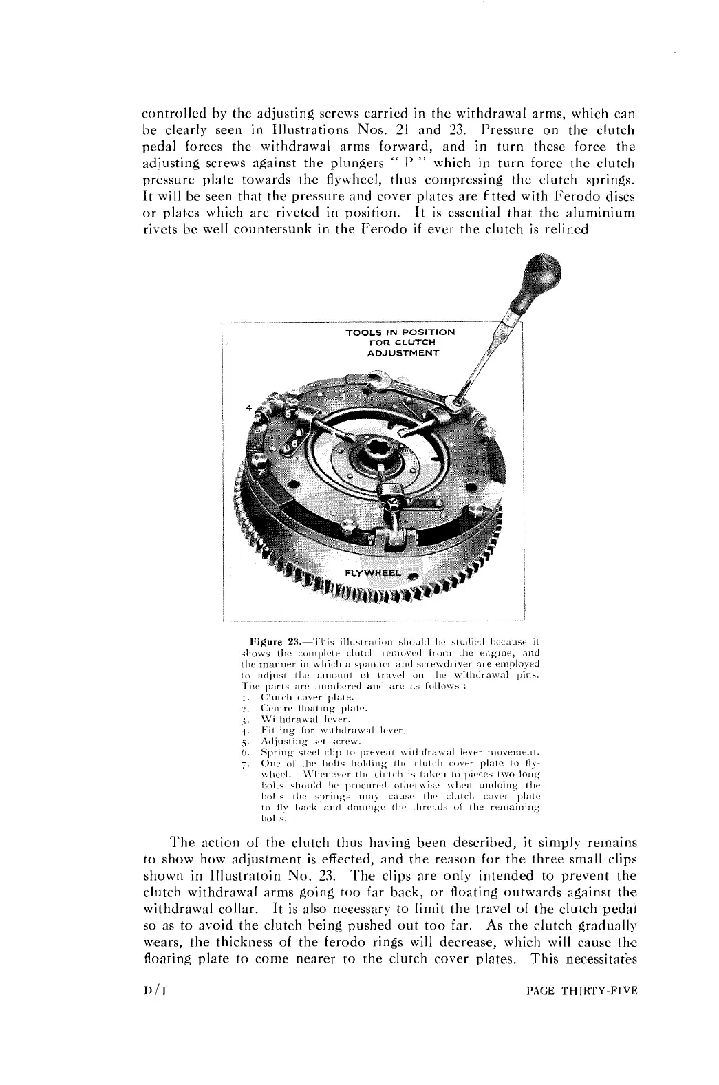
TOOLS
IN
POSITION
FOR
CLUTCH
ADJUSTMENT
The action of the clutch thus having b,een described, it simply remains
to show how adjustment is effected, and the reason for the three small clips
shown in Illustratoin No.
23.
'The clips are only intended to prevent the
clutch withdrawal arms going too far back, or floating outwards against the
withdrawal collar. It is also necessary to limit the travel of the clutch
pedal
so as to avoid the clutch being pushed out too far. As the clutch gradually
w'ears, the thickness of the ferodo rings will decrease, which will cause the
floating plate to come nearer to the clutch cover plates. This necessitates
1)
/
I
PAGE
THIRTY-FIVE