Illustr:~tion
No.
26
is a picture of the rear axle casing with the complete
differential assembly removed, and one axle shaft and hub removed as well.
Refore the differential can be withdrawn, it is necessary to withdraw the axle
shafts.
Axle Dismantlement.
First remove the wheels and brake drums. The
hub and
shaft can be withdrawn by refitting a wheel and pulling outwards
and the view obtained in Illustrntion No.
27
wil! be visible.
This shows th:lt
the axle shaft passes through the hollow axle casing, and the inner hub flange
runs on a large ball bearing. This bearing has to be periodically lubricated
which is effected by forcing a little grease through
a
nipple on the inside of
the hub recess. Under no circumstances should Gear
Oil
be used for this
bearing, but on the other hand
a
grease of the nature of vaseline is essential,
as for example Shell
R.B.
This grease will remain in the bexing and not be
flung out and find its way on to the brakes. The ball bearing is locked on
the axle tube by means of a ring nut and
tab washer. If ever the ring nuts
have to be slackened they can be driven off by a brass drift and hammer
Steel punches should never be used, except in absolute emergency.
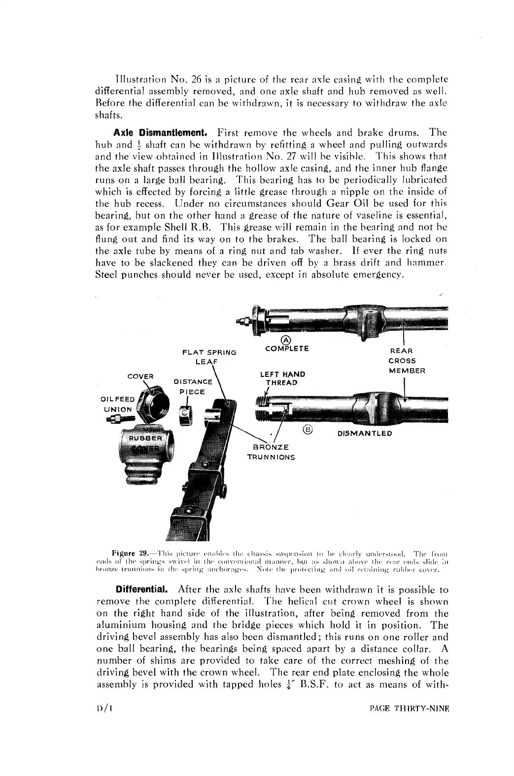
FLAT
SPRING
COMYLETE
LEAF
DISTANCE
\
LEFT
HAND
THREAD
I
REAR
CROSS
MEMBER
I
\
"/
DISMANTLED
BRONZE
TRUNNIONS
Differential.
After the axle shafts have been withdrawn it is possible to
remove the complete differential. 'The helical cut crown wheel is shown
on the right hand sidle of the illustration,
after being removed from the
aluminium housing and the bridge pieces which hold
it
in position. The
driving bevel assembly has also been dismantled; this runs on one roller and
one ball bearing, the bearings being spaced apart by a distance collar.
A
number of shims are provided to take care of the correct meshing of the
driving bevel with
thse crown wheel. The rear end plate enclosing the whole
assembly is provided with tapped holes
l"
B.S.F.
to act as means of with-
D
/
I
PAGE
THIRTY-NINE