H
THE
BEAll
AXU----
Operations
(a), (b)
and
(c)
merely
call for
the
fitting of
the
new
parts
in
the
positions
occupied by
the
old.
The
remaining
operations
entail special
precautions
and
are
detailed
subsequentl
y.
The
axle
or
half-shafts,
rear
hub bearlngs,
brake-
drums
and
shoe
mechanism can all be
dismantled
and
replaced
with
the
axle in position on
the
car.
Seetion
0.6
DISMANTLING THE AXLE
AND
REMOVING THE DIFFERENTIAL
ASSEMBLY
Remove
the
axle
from
the
car
as
detailed
in Section
H.4.
To dismantle
the
axle, first
remove
the
hub and
brake-d
ru
masse
mblj es as in Section H. I, and
the
brake
plates as in Section
H.2.
Remove
the
axle
half-shatts
as detailed in Section
H.3.
Remove
the
series
of
bolts joining
the
axle casing
and
cover
together
and carefully
part
them,
taking
care
to
see
that
both
halves
of
the
axle
are
suitably
supported
to
avoid damage
to
the
differential assembly.
The
withdrawal
of
the
axle
cover
from
the
casing
releases
the
differential and
crown
wheel
assembly,
which can now be
withdrawn.
Note
that
spacers
are
fitted
between
the
differential
bearlngs and
the
bearing housings and
that
they
are
important
as
they
control
the
position
of
the
differen-
tial assembly in
the
axle.
It Is essential
that
they
be replaced in
their
original
locations on assembly, so make a
note
of
the
positions
from
which
they
are
removed.
Note.-AII
original spacers are marked ols and njs.
It
must
also be
noted
that
the
axle casing and
cover
are
marked
on
the
surface of
one
of
the
outside
webs
or
tubes
with
one
of
the
following figures
:-Zero.
I, 2, 3, 4, 5, 6, all being positive.
Seetion
0.7
DISMANTLING THE DIFFERENTIAL
AND
CROWN
WHEEL
ASSEMBLY
When
the
differential assembly has been removed
from
the
axle casing, as
detailed
in Section H.6, it is
dismantled by bending back
the
tab
of
the
locking.
plate
of
the
bolt locating
the
differential pinion shaft,
withdrawing
the
bolt
and
removing
the
shaft.
The
differential pinions can
now
be
removed
from
the
differential cage by swinging
them
round
with
H.B
their
dished
thrust
plates until
they
register
with
the
openings in
the
differential cage,
through
which
they
can be
removed.
The
differential cage gears can
then
be
withdrawn
from inside
the
differential
through
the
openings,
togethe
r
wit
h
the
ir
th
rust
washers.
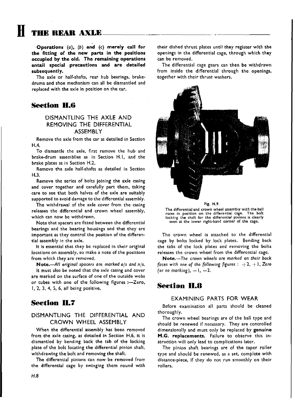
Fig. H.9.
The
differential and
crown
wheel assembly with
the
ball
races in position on
the
differential cage.
The
bolt
locki ng
the
shaft
for
the
differential pi
nlons
Is clearly
seen at
the
lower
right-hand
corner
of
the
cage.
The
crown
wheel
is
attached
to
the
differential
cage by bolts locked by lock plates. Bending back
the
tabs
of
the
lock plates and
removing
the
bolts
releases
the
crown
wheel
from
the
differential cage.
Note.-The
crown
wheels
are
marked on their bock
faces with one
of
the
following
figures;
-1-2,
-I-
I, Zero
(or no marking),
-1, -2.
Seetion
0.8
EXAMINING
PARTS
FOR
WEAR
Before
examination
all
parts
should be cleaned
thoroughly.
The
crown
wheel
bearings
are
of
the
ball
type
and
should be
renewed
if necessary.
They
are
controlled
dimensionally and
must
only
be replaced by
genuine
M.G.
repla.cements.
Failure
to
observe
this
in-
struction
will
only
lead
to
complications
later.
The
pinion shaft bearings
are
of
the
taper
roller
type
and should be
renewed,
as a
set,
complete
with
distance-piece, if
they
do
not
run
smoothly
on
their
rollers.
Wishvilles Classic
Automobile Library
 Loading...