the
flange.
Put
a little grease
01'1
the
sump
flange, this
will
ensure
future
easy removal.
Should
the
engine be
turned
while
the
sump
is
removed
or
drained,
thus
emptying
the
suction
passages.
the
pump
will have
to
be primed with oil
by disconnecting
the
delivery pipe on early engines.
Later
models have a special priming plug on
the
oil
pump
body.
The
main feed oil gallery may also be
primed
through
the
special plug provided for this
purpose
in
the
cylinder block above
the
pump
(see
Fig. A.S).
Seetion
1\..3
REMOVAL OF THE OIL PUMP
Drain
the
radiator
and slack off
the
top
and
bottom
water
hoses.
R.emove
the
front
engine mounting bolts holding
the
engine
bracket
to
the
rubber
block. Slightly
jack up
the
engine at
the
front.
This allows
the
pump
to clear
the
frame
member.
Note.-Qn
LHD
models the steering
column
passes
immediately
above
the oil pump. and it is not
possible
to
lift the engine without first raising the steering
column.
To
do this,
first
remove
the split pins and nuts
(rom
the
three bolts
at
the steering
column
universal
Joint,.
slacken
the bolt and nut
holding
the steering
column
to the
body
steady bracket, and take out the nut and bolt
from
the
support
clip under the
dash.
The
steering
wheel
may
now be
lowered
so that the
column
clears the oil pump,
and the
engine
may be lifted.
Detach
the
main
011
pipe from
the
filter
to
the
pump
on early models,
or
remove
filter bowl and
element
on
later
models.
R.emove
the
eight
bolts securing
the
pump
to
the
cylinder block. This will release
the
cover.
Lift off
the
cover
(rom
the
pump
body. This will
release
the
driven gear, which can easily be
withdrawn.
R.emove
the
pump
by gently tapping
the
side of
the
body and
withdrawing
it downwards.
Screw
a sultable
extraeto
r
into
the
end
of
the
driven
gear
shaft and
withdraw
it from
the
cylinder block if
it
is
required
to
remove
this.
Seetion
A.4
DISMANTLING,
REASSEMBLING
AND
REPLACING THE OIL PUMP
After
withdrawing
the
pump from
the
cyli
nder
block
as described in Section A.3,
remove
the
circlip securing
the
driving
gear
to
the
oil pump shaft and helical gear.
Using
a
suitable
drift,
tap
the
oil pump shaft and
gear
partly
through
the
driving gear.
Extract
the
key
and
gear
before
completely
removing
the
shaft, other-
wise
the
key will damage
the
bush.
C M.G. Midget (Serie$ .. TO
"),
lssue 3
(E)
79345-1
/S3
-THE
ENGINE
A
Clean all parts, examine and
check
for
wear.
The
gear
depth
Is 1·378
In.-·0016
11'1.-·0024 in.
(35
mm.-·04
mm.~·06
mm.)
with
a
diameter
of
1·2678
in.+ool
in. (32'2
mm.+025
mm.).
The
housing
depth
is 1·378
in.+·0012
in. (3S
rnm.'}
·03 mm.) with a
bore
of 1·2795
in.+·ool
in.-·OOO6 in.
(32-5
mm.+-015
mm.-·OIS
mm.).
This results in a
gear
end float of
-0016
in.
to
·003S
In. (-04mm.
to·09
mm.) with
the
end
cover
fitted,
and a rad
ia] cfearance of ·0056 in. to ·0064 in. (,145 mm,
to
·162 mrn.). The backlash
between
the
teeth
Is
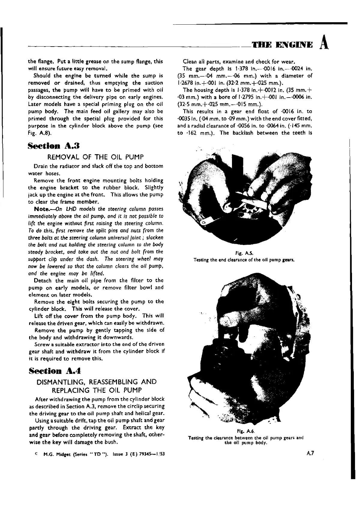
fig.
AS.
Testing
the end
clearance
of the
011
pump
gears.
fig.
A.6.
Testing
the
clearance
between
the oil pump gears
and
the off pump
body.
A.7
Wishvilles Classic
Automobile Library
 Loading...