-------------ELECTRI~1U
EQUIPMENT
N
between
the
back of
the
armature
"A"
and
the
regulator
frame"
B."
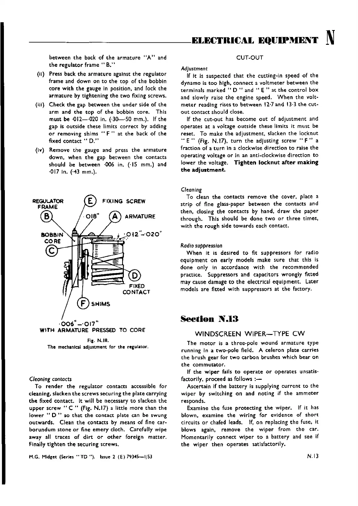
(ii) Press back
the
armature
against
the
regulator
frame and down on to
the
top of
the
bobbin
core
with
the
gauge in position, and lock
the
armature
by
tightening
the
two
fixing screws.
(iii)
Check
the
gap
between
the
under side of
the
arm and
the
top
of
the
bobbin core. This
must be '012-·020 in. (·30--·50 mm.). If
the
gap is
outside
these
limits
correct
by adding
or
removing
shims"
F"
at
the
back of
the
fixed contact ..
D."
(iv) Remove
the
gauge and press
the
armature
down, when
the
gap between
the
contacts
should be between ·006 in. (·15 mm.) and
·017 In. ('43 mm.).
FIXING
SCREW
ARMATURE
F SHIMS
·006"
-'017"
WITH
ARMATURE
PRESSED
TO
CORE'
FiC.
N.IS.
The mechanical adjunment for the regulator.
Cleaning
contacts
To
render
the
regulator contacts accessible for
clean ing. slacke n
the
screws securlng
the
piate carrylng
the
fixed contact. It will be necessary
to
slacken
the
upper
screw"
C " (Fig. N.17) a little
more
than
the
lower"
0 " so
that
the
contact plate can be swung
outwards.
Clean
the
contacts by means of fine car-
borundum
stone
or
fine
emery
cloth. Carefully wipe
away all traces of
dirt
or
other
foreign
matter.
Finally
tighten
the
securing screws.
M.G. Midget (Series .. TD "). Issue 2
(E)
79).045-1/53
CUT-OUT
Adjustment
If It Is suspected
that
the
cutnng-ln speed
of
the
dynamo is
too
high.
connect
a
voltmeter
between
the
te rminals mar ked " D " and .. E " at
the
control box
and slowly raise
the
engine speed.
When
the
volt-
meter
reading rises
to
between
12·7and 13·3
the
cut-
out
contact should close.
If
the
cut-out
has become
out
of adjustment and
operates
at a voltage outside
these
limits it must be
reset. To make
the
adjustment, slacken
the
locknut
..
E"
(Fig.
N.ll),
turn
the
adjusting screw ..
F"
a
fraction of a
turn
in a clockwise direction
to
raise
the
operating voltage
or
In an anti-clockwise direction
to
lower
the
voltage.
Tighten
locknut
after
making
the
adjustment.
C'eaning
To clean
the
contacts remove
the
cover. place a
strip
of fine glass-paper between
the
contacts and
the
n, closlng
the
contacts by hand. draw
the
paper
through.
This should be
done
two
or
three
times,
with
the
rough side
towards
each contact.
Radio
suppression
When
it is desired
to
fit suppressors for radio
equipment
on early models make
sure
that
this is
done
only in accordance with
the
recommended
practice. Suppressors and capacitors wrongly fitted
may cause damage
to
the
electrical equipment. Later
models
are
fitted
with
suppressors at
the
factory.
Seetion
N
.13
WINDSCREEN WIPER-TYPE
CW
The
motor
is a
three-pole
wound
armature
type
running In a two-pole field. A celeron plate carries
the
brush. gear for
two
carbon brushes which bear on
the
commutator.
If
the
wiper
fails
to
operate
or
operates
unsatis-
factorily. proceed as follows
:-
Ascertain If
the
battery is supplying
current
to
the
wiper
by switching on and noting If
the
ammeter
responds.
Examine
the
fuse
protecting
the
wiper. If it has
blown, examine
the
wiring
for
evidence of
short
circuits
or
chafed leads. If, on replacing
the
fuse, it
blows again. remove
the
wiper
from
the
car.
Momentarily connect
wiper
to
a battery and see if
the
wiper
the
n
operates
satisfactori ly.
N.13
Wishvilles Classic
Automobile Library
 Loading...