© MHG Heating Ltd
32
MHG Heating Ltd Unit 4 Epsom Downs Metro Centre, Waterfield, Tadworth, Surrey KT20 5LR
Telephone 08456 448802 Fax 08456 448803 Email info@mhgheating.co.uk
Web www.mhgheating.co.uk
010711
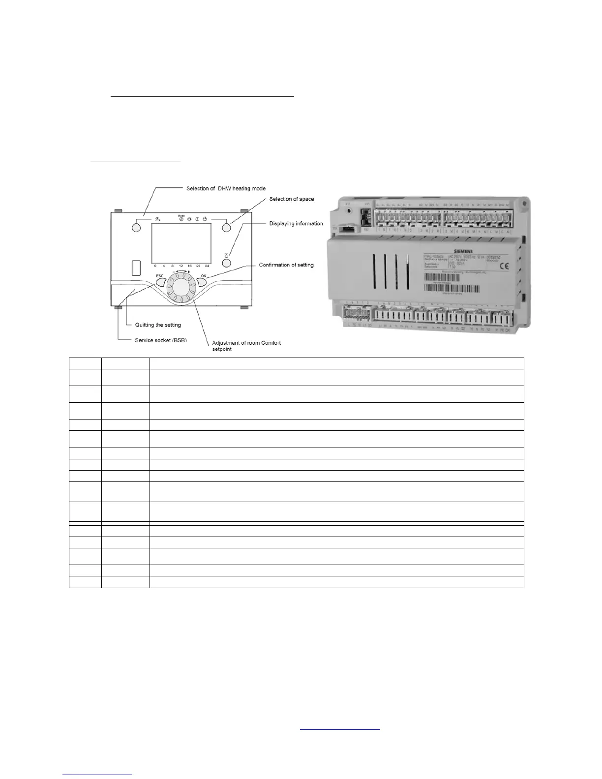
8.12 Separately Housed RVS43 Cascade Manager
Terminal Designation
Tag Voltage Description/Operation/Function
H1 <25V
0-10 Volt Input via BMS/Volt Free Enable via Room Thermostat/BMS
(M terminal used to create circuit)
B70/B4 <25V
System Return Sensor (QAD36)
(To be positioned on boiler side of system Low Loss Header)
B3 <25V
Hot Water Sensor (QAZ36)/Volt Free Enable via Calorifier Thermostat/BMS
(Parameter alteration required if Volt Free Enable Used)
M <25V Ground Connection for all Sensors/Inputs
B10 <25V
System Flow Sensor (QAD36)
(
To be positioned on system side of system Low Loss Header)
B9 <25V Outside Air Sensor (QAC34) or (3000Ω Substitute Resistor = -1
0
C)(Mounted on North Facing Wall)
MD <25V QAA75/78 Room Unit (BSB Ground)
A6 <25V QAA75/78 Room Unit (BSB Data)
MB <25V
Boiler Communication
(LPB Ground connected in parallel to boiler mounted OCI420 Clips)
DB <25V
Boiler Communication
(LPB Data connected in parallel to boiler mounted OCI420 Clips))
Q3 230V Hot Water Charging Pump/3 Way Valve Output (Max 2 Amp)
Q1 230V Heating Pump Output (Max 2 Amp)
F1 230V
Power Input for Heating and Hot Water Pump Outputs
(To be linked to Live Input)
L 230V Permanent Live (Max 6 Amp)
N 230V Permanent Neutral