EasyManua.ls Logo

Mhouse wg2s User Manual

Mhouse wg2s
132 pages
Go to English
To Next Page IconTo Next Page
Page #1 background imageLoading...
Page #1 background image
MhouseKit
WG2S
0682
FR - Instructions et avertissements pour l’installation et l’utilisation
EN - Instructions and warnings for installation and use
IT - Istruzioni ed avvertenze per l’installazione e l’uso
PL -Instrukcjeiostrzeżeniadoinstalacjiiużytkowania
Kit complet pour automatiser un portail battant

Table of Contents

Questions and Answers:

Mhouse wg2s Specifications

General IconGeneral
BrandMhouse
Modelwg2s
CategoryGate Opener
LanguageEnglish

Summary

GENERAL SAFETY WARNINGS AND PRECAUTIONS (STEP 1)

KNOWLEDGE OF PRODUCT AND PREPARATION (STEP 2)

Product Description and Intended Use

Details the WG2S automation system and its intended use for residential swing gates.

Components for Complete System

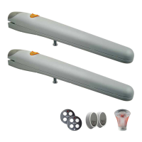
Lists and illustrates the components included in the WG2S kit for a complete automation system.

PRELIMINARY CHECKS FOR INSTALLATION (STEP 3)

Gate Suitability and Environment Checks

Ensures gate mechanical structure, environment, and manual movement are suitable for automation.

Product Application Limits

Verifies gate dimensions, weight, and opening angle are within the WG2S product limits.

Product Durability Estimation

Explains how to estimate product lifetime based on usage factors and graph.

PRELIMINARY CHECKS FOR INSTALLATION (STEP 4)

Establish Device Installation Positions

Locates approximate positions for installation of each device in the automation system.

Preparing Electric Cables

Details the process for preparing connection cables, including referring to diagrams and cable specifications.

INSTALLATION: ASSEMBLY AND CONNECTION OF COMPONENTS (STEP 5)

Installing the WG1SK Gearmotor

Step-by-step guide for securely installing the WG1SK gearmotor onto the gate leaf and supports.

INSTALLATION: ASSEMBLY AND CONNECTION OF COMPONENTS (STEP 6)

Installing the CL2S Control Unit

Instructions for selecting the position and mounting the CL2S control unit, including cable routing.

Connecting PH100 Photocell

Details on positioning and connecting the PH100 photocells to the system.

Connecting FL100 Flashing Light

Guide for positioning and connecting the FL100 flashing light to the system.

Electrical Connections to CL2S Control Unit

Instructions for making electrical connections of various devices to the CL2S control unit.

PROGRAMMING (STEP 7)

Power Supply and Initial Checks

Connecting power and performing initial checks on the control unit and devices.

Learning Devices and Gate Angles

Procedure for control unit to learn connected devices and gate opening/closing limits.

Transmitter Checks and Settings

Testing radio transmitters and adjusting operational parameters like speed and cycle mode.

TESTING AND COMMISSIONING (STEP 8)

System Testing

Performing tests on the automation system to ensure safety and correct operation of all components.

System Commissioning

Finalizing the automation setup, including documentation and providing information to the owner.

FURTHER INFORMATION (STEP 10)

10.1 Advanced Settings

Setting control unit parameters using the radio transmitter, covering pause time, pedestrian opening, etc.

10.2 Optional Accessories

Information on optional accessories that can integrate with the WG2S automation system.

10.3 Adding or Removing Devices

Adding Optional Photocell

How to install additional photocells and assign addresses using jumpers.

ECSBus Device Management

Connecting, recognizing, and managing devices using the ECSBus system.

STOP Input Configuration

Connecting and configuring devices for the STOP input, including safety considerations.

10.4 Memorizing Radio Transmitters

Remote Transmitter Memorisation

Method to memorize new transmitters using an existing programmed transmitter.

Deleting Radio Transmitters

Procedures for deleting specific or all radio transmitters from the system memory.

10.5 Troubleshooting

10.6 Diagnostics and Signals

Photocell Diagnostics

Interpreting the LED status on photocells to diagnose operation or faults.

Flashing Light Status Indicators

Understanding the flashing patterns of the indicator light to diagnose system status or errors.

Control Unit LED Indicators

Interpreting the LEDs on the control unit for normal operation, faults, and status variations.

Installing PR1 Buffer Battery

Installing PF Solar Power System

Maximum Cycles Per Day Calculation

TECHNICAL SPECIFICATIONS OF PRODUCT COMPONENTS

APPENDIX 1 - CE DECLARATION OF CONFORMITY

USER'S GUIDE (STEP 11)

11.1 Safety Instructions

Essential safety rules for operating the gate automation system and user precautions.

11.2 Gate Control

Operating the gate using the radio transmitter or an optional selector switch, including safety device behavior.

11.3 Manually Releasing or Locking the Gearmotor

Procedure to manually move the gate in case of power failure or system malfunction.

11.4 User Maintenance Operations

List of basic maintenance tasks that can be performed by the user on the automation system.

11.5 Remote Control Battery Replacement

Guide for replacing the battery in the remote control transmitter when the charge is low.

11.6 Installing the Remote Control Support

Instructions for installing the dedicated support for the remote control transmitter.

APPENDIX 2 - CE DECLARATION OF CONFORMITY

Related product manuals