Do you have a question about the Mhouse SL10S and is the answer not in the manual?
Critical instructions and warnings for personal safety during installation and use.
Specific warnings related to installation procedures, electrical connections, and product handling.
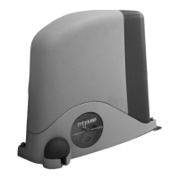
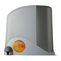
Describes the SL1S-SL10S kit and its intended use for residential sliding gates.
Lists the components included in the SL1S-SL10S automation kit.
Verifies gate mechanical suitability and environmental conditions for automation.
Defines gate dimensions, weight limits, and estimates product lifetime.
Guides on establishing optimal positions for system devices and cable raceways.
Ensures all necessary equipment, materials, and site preparation are completed.
Details preparing electric cables, checking diagrams, and determining types and lengths.
Step-by-step guide for installing the gearmotor on a gate without an existing rack.
Step-by-step guide for installing the gearmotor on a gate with an existing rack.
Instructions for installing and connecting the PH100 photocell pair.
Guide for mounting and wiring the FL100 flashing indicator light.
Details the electrical connections required for the control unit.
Instructions for connecting the automation to the electrical mains.
Performs initial checks on system LEDs and connected devices.
Explains how the control unit recognizes connected devices via the ECSBus.
Verifies gate leaf movement and checks limit switch functionality.
Verifies the functionality of the radio transmitters.
Covers selecting leaf speed and operating cycle modes.
Details the testing procedures for the automation system.
Outlines the steps for commissioning the automation system.
Procedures for regular maintenance checks and user-admissible operations.
Instructions on how to properly dispose of the product and its components.
Covers parameter settings and checking via radio transmitter.
Information about optional accessories like buffer battery and solar power.
Instructions for installing and connecting the PR1 buffer battery.
Instructions for connecting the PF solar power supply system.
Describes the ECSBus system for connecting devices via two wires.
Procedure for memorizing transmitters using Mode 1.
Procedure for memorizing transmitters using Mode 2.
Method for memorizing new transmitters using an existing one.
Procedure for deleting a specific radio transmitter.
Procedure for deleting all memorized radio transmitters.
Table listing common symptoms and their probable causes and solutions.
Explains the meaning of the "SAFE" LED status on photocells.
Describes the signals from the flashing light indicating operational status or anomalies.
Detailed technical specifications for the SL1SC and SL10SC gearmotors.
Technical specifications for the PH100 photocell system.
Technical specifications for the FL100 indicator light.
Technical specifications for the GTX4 remote control transmitters.
Provides the CE declaration of conformity for the SL1S and SL10S automation.
Safety instructions for users of the automated gate system.
Explains how to control the gate using the radio transmitter and selector.
Instructions on how to manually release or lock the gearmotor for gate operation.
Lists maintenance tasks that can be performed by the user.
Guide on how to replace the battery in the remote control transmitter.
Instructions for installing the support for the remote control.
Form for the person responsible for commissioning to declare conformity.
| Brand | Mhouse |
|---|---|
| Model | SL10S |
| Category | Gate Opener |
| Language | English |