3
Short-term delivery l Subject to technical modications
1 GENERAL INFORMATION
Das DC-Puffermodul ist im bestimmungsgemäßen Gebrauch für die Überbrückung einer DC-Spannungsversorgung bei Spannungs-
ausfall bestimmt. Das Puffermodul wird hierzu von einem externen, geregelten DC-Netzteil aufgeladen.
1.1 GENERAL SAFETY INSTRUCTIONS
Note
Read these instructions before installing or using the power supply. The instructions must be adhered to.
Disregarding the instructions may void the warranty!
Danger
The back-up module may only be put into operation and maintained by qualified electricians. Improper
handling of the voltage or the capacitors can lead to electric arcing and serious burns.
Warning
Make sure the unit is de-energised before carrying out any work on it!
All incoming and outgoing lines must be sufficiently sized and protected.
1.2 SHORT DESCRIPTION
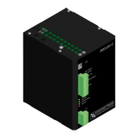
The RDCUSV C series DC back-up module has an ultracapacitor as an energy storage device inside the enclosure. This capacitor
is charged during normal operation by an external regulated DC power supply unit. If the DC supply is interrupted the energy of the
ultracapacitors is released in a controlled manner. The load is fed from the back-up module until it has been completely discharged.
The back-up time is dependent upon the state of charge of the capacitor and the load current.
The back-up module has the following features:
Long-life ultracapacitors for maintenance-free operation
Microcontroller-assisted charging and discharging of ultracapacitors
Parameterisation via USB interface
Operational and state of charge monitoring via potential-free contacts and LEDs
2 ASSEMBLY AND CONNECTION
2.1 ASSEMBLY
Install the unit in such a way that adequate air circulation is ensured. The specified ambient temperature must not be exceeded. The
maximum installation altitude at which there is no loss in performance is 2000 metres above sea level.
NOTE
Maintain a distance of at least 40 mm from the enclosure to neighbouring devices to ensure adequate air
circulation. The area under the enclosure must be free from heat sources.
NOTE
Cover the unit during installation to ensure no drill chips get on to or into the unit.
Risk of short circuit
NOTE
This unit is a built-in device. It may only be operated in dry rooms.
The unit is designed for contamination level 2.
Snap-on clips for 35 mm standard DIN rails
DIN EN 50022 (NS 35 x 15 / 7.5mm)
 Loading...