5
Short-term delivery l Subject to technical modications
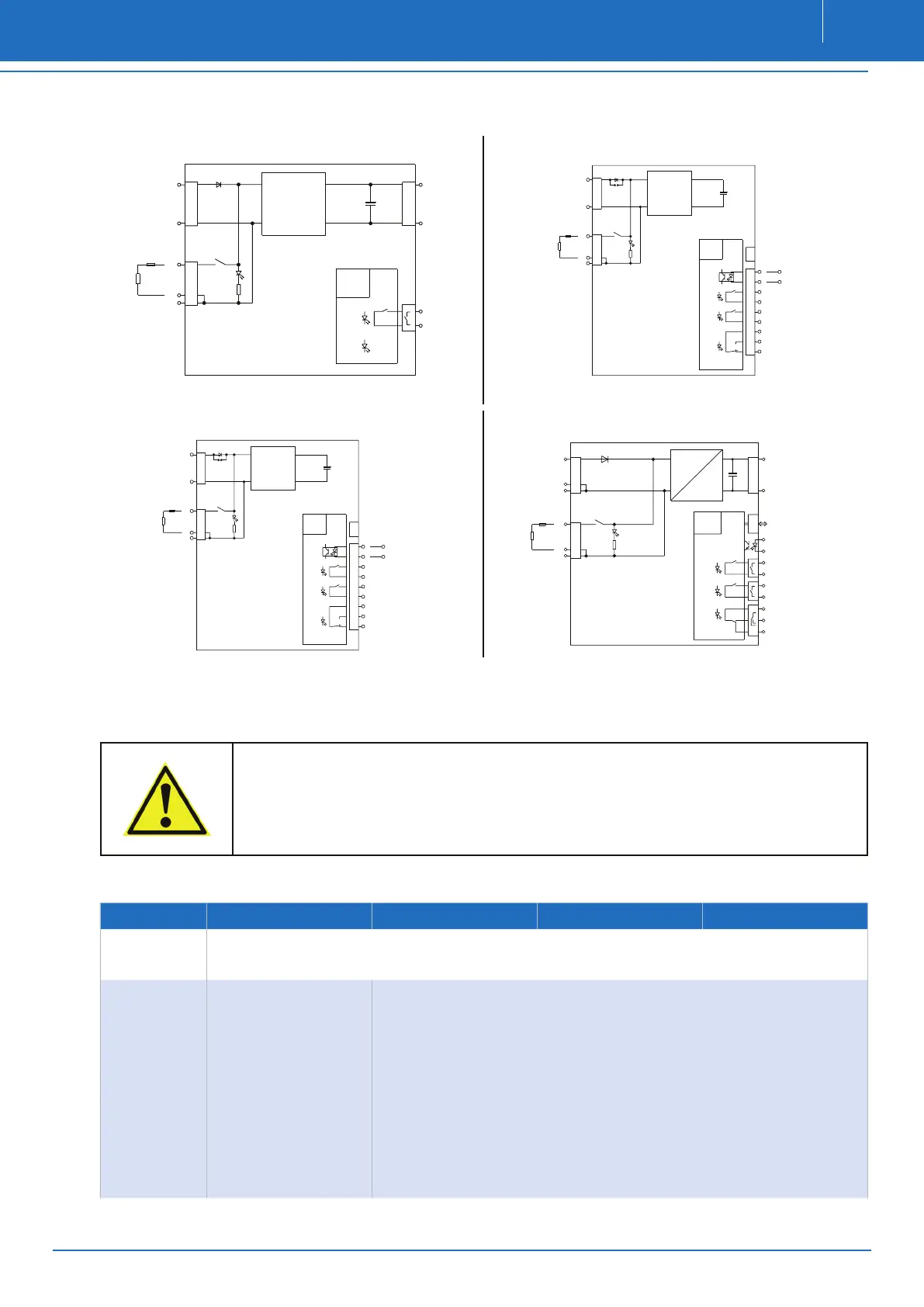
2.4 PRINCIPLE CIRCUIT DIAGRAM
RDCUSV 3C1
LAST
Ua
+
-
-
K1
IV-o.k.
DC 30V
0,5A
Uc>
LED3
C1DC-DC converter
LED1
Operation
D1
C
+
F
LED2
-
Ue
µC
K
+
-
RDCUSV 5C5
F
DC 30V/0,5A
UE
-
-
+
K1
2
LAST
Error
USB
5
+
6
-
4
7
UC>
9
IV-o.k.
SHUT-DOWN
K
K
DC 30V/0,5A
K
DC-DC converter
LED4
Operation
D1
J1
-
1
UA
DC 30V/0,5A
LED3
µC
C1
I/O
8
+
3
LED1
LED2
RDCUSV 10C10
F
DC 30V/0,5A
UE
-
-
+
K1
2
LAST
Error
USB
5
+
6
-
4
7
UC>
9
IV-o.k.
SHUT-DOWN
K
K
DC 30V/0,5A
K
DC-DC converter
LED4
Operation
D1
J1
-
1
UA
DC 30V/0,5A
LED3
µC
C1
I/O
8
+
3
LED1
LED2
RDCUSV 20C8
LAST
Ua
+
-
-
K1
Line
DC 30V/0,5A
Uc>
LED3
DC converter
LED1
Operation
C
+
-
K
DC 30V/0,5A
C1
+
LED4
K
Error
DC 30V/0,5A
Shutdown
PC
USB
DC-
1.1
1.2
1.3
1.4
1.5
1.6
1.7
1.8
1.9
-
-
F
LED2
Ue
µC
K
3 INITIAL OPERATION
The unit is put into operation through switch-on of the DC supply by means of the ‘IV’ terminal.
NOTE
For units built into systems in which overvoltages are applied for testing (e.g. in accordance with EN60204-1
/ VDE0113 part 1 19.4 Voltage testing) the unit must be disconnected from the test apparatus before the
voltage is applied.
(Original text EN60204-1 : Parts not designed for this test voltage must be disconnected during testing.)
3.1 DISPLAYS AND MESSAGES
Typ RDCUSV 3C1 RDCUSV 5C5
RDCUSV 10C10
RDCUSV 20C8
LED- Anzeige
Operation Green LED lights up if system voltage is available.
IV o.k. Green LED lights up if external supply is available.
Uc > Green LED lights up if capacitor energy is > 80%.
LED- Anzeige
Green LED goes out if:
Capacitor energy is 30%
LED blinks slowly
(0,8Hz):
During charging until
80% of total capacitor
energy has been reached
LED blinks rapidly (3,2
Hz):
If capacitor is completely
discharged
Error Red LED lights up if: - overvoltage on the internal capacitor
- over- or undervoltage on the IV terminal
- output overvoltage