P341/EN AD/F43 Update Documentation
(AD) -18
MiCOM P341
Phase Overcurrent (Overcurrent)
Phase O/C: Sub Heading
I>1 Function:
Disabled
DT
IEC S Inverse
IEC V Inverse
IEC E Inverse
UK LT Inverse
UK Rectifier
RI
IEEE M Inverse
IEEE V Inverse
IEEE E Inverse
US Inverse
US ST Inverse
I>1 Direction:
Non-Directional
Directional Fwd
Directional Rev
I>1 Current Set: 0.08…4.00 In
I>1 Time Delay: 0.00…100.00s
I>1 TMS: 0.025…1.200
I>1 Time Dial: 0.01…100.00
I>1 K (RI): 0.10…10.00
I>1 Reset Char: DT/Inverse
I>1 tRESET: 0.00…100.00s
I>2 as I>1
I>3 Status: Disabled/Enabled
I>3 Direction:
Non-Directional
Directional Fwd
Directional Rev
I>3 Current Set: 0.08…10.00 In
I>3 Time Delay: 0.00…100.00s
I>4 as I>3
I> Char Angle: -95…+95
o
I >Function Link:
Bit 0 = VTS Blocks I>1
Bit 1 = VTS Blocks I>2
Bit 2 = VTS Blocks I>3
Bit 3 = VTS Blocks I>4
Bit 4, 5, 6 & 7 are not used
Binary function link string, selecting which
overcurrent elements (stages 1 to 4) will be
blocked if VTS detection of fuse failure
occurs.
Inverse time (IDMT) characteristic
IDMT characteristics are selectable from a
choice of four IEC/UK and five IEEE/US curves
as shown in the table below.
The IEC/UK IDMT curves conform to the
following formula:
t = T x
K
(/
s
)
- 1
+ L
The IEEE/US IDMT curves conform to the
following formula:
t = TD x
K
(/
s
)
- 1
+ L
Where:
t = Operation time
K = Constant
= Measured current
S
= Current threshold setting
= Constant
L = ANSI/IEEE constant (zero for IEC/UK
curves)
T = Time multiplier setting for IEC/UK curves
TD = Time dial setting for IEEE/US curves
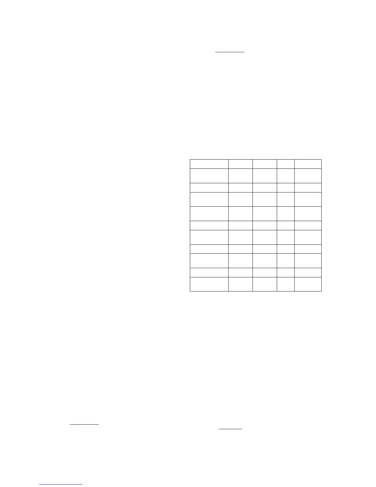
IDMT characteristics
IDMT Curve Stand. K
L
Standard
inverse
IEC 0.14 0.02 0
Very inverse IEC 13.5 1 0
Extremely
inverse
IEC 80 2 0
Long time
inverse
UK 120 1 0
Rectifier UK 45900 5.6 0
Moderately
inverse
IEEE 0.0515 0.02 0.114
Very inverse IEEE 19.61 2 0.491
Extremely
inverse
IEEE 28.2 2 0.1217
Inverse US-C08 5.95 2 0.18
Short time
inverse
US-C02 0.16758 0.02 0.11858
The IEC extremely inverse curve becomes
definite time at currents greater than 20 x
setting. The IEC standard, very and long time
inverse curves become definite time at
currents greater than 30 x setting.
For all IEC/UK curves, the reset characteristic
is definite time only.
For all IEEE/US curves, the reset characteristic
can be selected as either inverse curve or
definite time.
The inverse reset characteristics are
dependent upon the selected IEEE/US IDMT
curve as shown in the table below.
All inverse reset curves conform to the
following formula:
tRESET =
TD x S
(1 - M
2
)
in seconds
Where:
TD = Time dial setting for IEEE curves