Update Documentation P341/EN AD/F43
MiCOM P341
(AD) -29
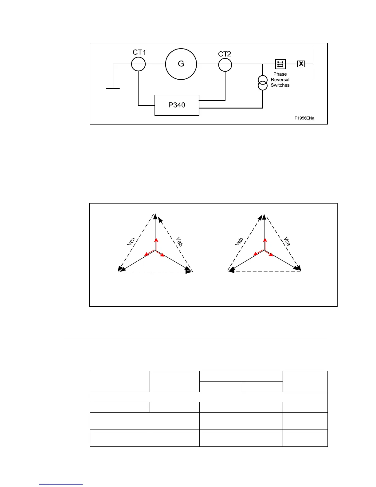
Figure 1: Case 1 : Phase reversal switches affecting all CTs and VTs
All the protection functions that use the positive and negative sequence component of
voltage and current will be affected (NPS overcurrent and NPS overvoltage, thermal
overload, voltage transformer supervision). Directional overcurrent is also affected as the
polarizing signal (Vbc, Vca, Vab) is reversed by the change in phase rotation. Note, CT2 is
not applicable to P341/2 relays only P343/4/5 relays which include differential protection.
The relationship between voltages and currents from CT1 for the standard phase rotation
and reverse phase rotation are as shown below.
Standard ABC rotation
Vc Vb
Vbc
Va
Ia
Ib
Ic
Case ¼ reverse ACB rotation
Vb Vc
Vbc
Va
Ia
Ic
Ib
P1957ENa
Figure 2: Standard and reverse phase rotation
2.3.2 System config settings
The following settings are available in the “SYSTEM CONFIG” menu as follows. These new
settings are available for each of the four protection setting groups.
Setting Range
Menu Text Default Setting
Min. Max.
Step Size
System Config
Phase Sequence Standard ABC Standard ABC, Reverse ACB N/A
VT Reversal No Swap
No Swap, A-B Swapped,
B-C Swapped, C-A Swapped
N/A
CT1 Reversal No Swap
No Swap, A-B Swapped,
B-C Swapped, C-A Swapped
N/A